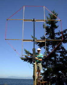
My ten foot air-core receiving loop was originally designed and constructed for NDB DXing. More recently, it has been pressed into service for LOWFER DX work. The loop has been instrumental in achieving two notable low-frequency receptions - the first Trans-Pacific reception of ZL (New Zealand) amateur radio LF signals in North America as well as establishing the present long-distance record for LOWFER reception in North America, the 1-watt signal of "NC" from North Carolina to British Columbia, an overland distance of 2,360 miles. The loop is a good performer!
OVERVIEW Basically the loop is like most antennas, just a big resonant tuned circuit probe that is coupling into the radio signal's electromagnetic field. Electrically, the loop looks like the tuned circuit shown here. The 1-turn link couples signals out of the main loop to be fed to the receiver. The loop is tuned (signals peaked) with the variable tuning capacitor.
The frequency tuning range of the loop basically depends on the number of turns in the main coil and the size of the tuning capacitor. My ten-foot loop has 14 turns of #20 plastic coated stranded copper wire. The tuning capacitor is a 400pf dual variable with both sections connected in parallel. The tuning range of the loop is from 180kHz to 410kHz approximately. By adding a 250pf silver mica fixed capacitor in parallel with the loop, tuning will drop to around 135kHz at the low end, perfect for the new 136kHz band when it arrives. Conversely, by shorting out the first turn in the loop, the lower end of the broadcast band can be tuned. Reducing the number of turns will raise the overall frequency tuning range. For the BCB DXer, I would suggest reducing the number of turns to 8 or 9. Going with even fewer turns, the loop would make a great low-noise, directional 160m receiving antenna.
CONSTRUCTION- The loop frame is built from 3 x 3/4 Western Red Cedar. Redwood, Yellow Cedar or even marine-grade plywood should serve equally well. Perhaps you have something similar, indigenous to your area that could be procurred. The frame must be strong and weather resistant and of course the lighter you can make it, the better. The frame must not be metallic! The four legs of the frame are all 10 feet in length. At each crossover point, a half-lap joint has been cut to join the frame together. Each joint has been screwed with a single brass wood screw and glued with two-part exterior water-proof glue. The loop has been outdoors for about 4 years now and has survived several dozen severe windstorms coming directly off the ocean. Part of its "survivability" is due to the flexibility of its 2" plastic ABS support mast. This allows the mast to absorb the brunt of the wind blasts.
There have been several storms where the loop has been bent-over at a 30 degree angle for long periods yet it continues to survive, so far!
Attached to the end of each frame leg is a wooden "wire-comb" that is used to keep the loop wires in alignment. The spacing between each wire will determine the length of the comb. The wider the spacing, the better, but a point is quickly reached where the spacing makes the loop windings too "floppy". Each turn of my loop is spaced .25 inches apart. The wooden combs are 1.5" X 5" and have been glued and dowelled into a groove cut in the end of each frame leg. They could just as effectively be glued and screwed to the outside ends of all legs.
In order to effectively capture each coil winding, the combs were drilled with the correct number of holes and then the top part of the comb was cut off, leaving the bottom half of each hole to act as a groove to capture and hold the wire.
Once the loop was wound, a heavy coating of the same two-part waterproof glue used earlier was liberally applied over the wires where they lay on the combs, anchoring them firmly in place.The pickup loop (fed to the receiver via 50 ohm coaxial cable) is a 1-turn loop wound around the inside of the main loop. It is spaced approximately 6" inside the main winding.
Wider spacing will result in reduced signal pickup as well as sharper tuning, necessitating frequent re-peaking. An advantage of the single turn pickup loop is that the loop is completely electrically isolated from the main station ground, often a source of induced noise pickup. In its present configuration, it is only necessary to re-peak the tuning capacitor every 50kHz approximately. When DXing the NDB band (200-530kHz) it can often take an hour or more to carefully tune through the chosen 50kHz segment before re-tuning for the next range. If used for LOWFER DX work, it is simply a matter of 'set and forget' tuning!
PERFORMANCE As outlined earlier, the ten-foot loop has proven to be a good performer right from the start. Preamplifiers are often used with small homebrew loops to compensate for their low level of signal pick-up. The large aperture of this loop provides more than enough signal pick-up. No preamplification is used or required. Preamp-induced overload or cross-mod problems caused by nearby "blowtorch" signals are non-existent. The limiting factor of reception is always local or (more often than not) atmospheric noise, easily reached with the large aperture.
In an electrically noisy location, the loop can often be used to best advantage as a steerable "null" to eliminate or vastly reduce the noise source.
In quiet locations, the loop can be turned to enhance signal pick-up. Maximum signal pick-up is in the plane of the loop. For more information on loop antennas, see the links section below and ....good looping!
A NEW 8' AIR CORE LOOP FOR L.F.
After almost 10 years of good service, my 10' loop was recently destroyed in a huge mid-winter storm. The failure point was the PVC tubing that had eventually become work-hardened over the years and brittle enough to snap off just above the support post. I decided to rebuild a slightly smaller, more "storm-friendly" version, an 8' open-frame air core loop.
Each arm of the frame is an 8' length of 3/4" x 2 3/4" Western Red Cedar. The four half-lap joints were cut 29" in from the ends of each arm. All joints were screwed and glued with two-part waterproof glue before applying two coats of exterior-grade polyurethane varnish.
Electrically, the loop consists of 13 turns of vinyl-coated #22 stranded copper wire, spaced 1/4" per turn. The measured inductance of the loop is 1.3mH. The one-turn pick-up loop is spaced 5.5" inside the main winding and fed directly with 50 ohm cable. Using a two-section air variable (10-670pf), the loop tunes from 180 kHz to 450 kHz. Two weatherproofed terminals emerging from the capacitor box allows a small 1000pf silver mica capacitor to be clipped across the tuning capacitor. With the variable set at mid-range, the loop can be tuned to 137 kHz (2200m band) +/- several kHz for peaking.
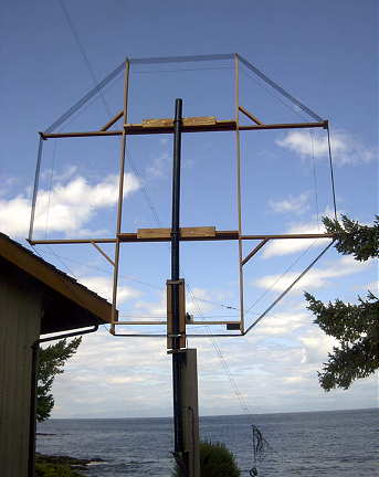
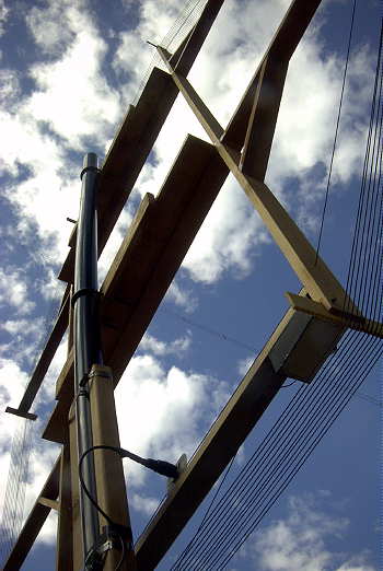
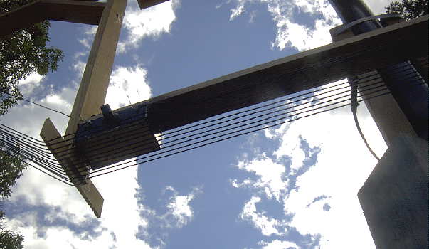
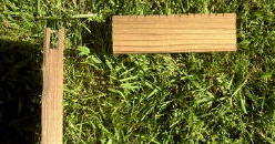
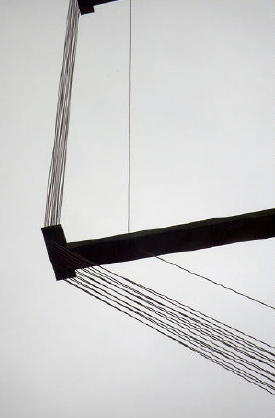
Some of the construction details can be seen in these two images showing the frame support method as well as the location of the tuning capacitor. Be sure to make the capacitor's box weatherproof by sealing the edges with lots of silicone sealer as well as properly weatherproofing the connector.
LOOP LINKS
RECEIVING LOOP AERIALS FOR 1.8MHZ (VK5BR) - Plans for 160m RX loop and preamp
SUPERLOOP RECEIVING ANTENNA FOR 136kHz - A nice air - core loop from G3LDO
A LOOP 'CALCULATOR' - A nifty way to find the tuning range of your loop before you build!
THINKING ABOUT IDEAL LOOPS - A detailed discussion of loop dynamics
DOUG'S RADIO-ELECTRONICS LOOP ANTENNA PAGE - Various loop characteristics
W8JI's LOOP PAGE - Good facts about shielded loops
160 / 80m COAXIAL RECEIVING LOOPS - Practical construction data
G4CNN's Loop Page - G4CNN's LF Loop Tips
YAHOO! 'LOOPS' DISCUSSION GROUP - Talk with others about all kinds of loops!
HARDCORE DX SITE - Contructing a 160/80m shielded loop.
![]()