MF Operation at DF0WD (and elsewhere..)by Wolfgang Buescher, DL4YHF last updated: January 2018. |
||||||||||
|
Contents
Initial reception tests
During initial reception tests on the UK's former 500 kHz band,
it became obvious that the 'station ground' (connected to mains ground)
carried a lot of noise, most likely from switching mode power supplies,
compact fluorescent lamps, and similar. The receiver made a buzzing sound,
and weak amateur radio signals were completely masked.
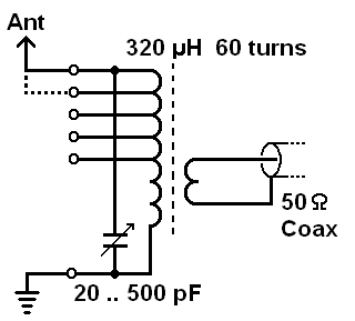
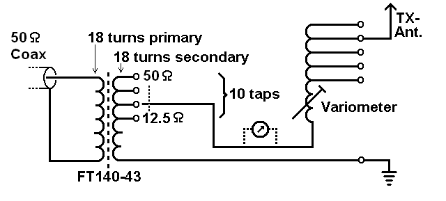
An important feature of this LC parallel configuration is its ability to act
as a transformer. The antenna, and its counterpoise ("Earth") are completely
isolated from the noisy "mains" ground.
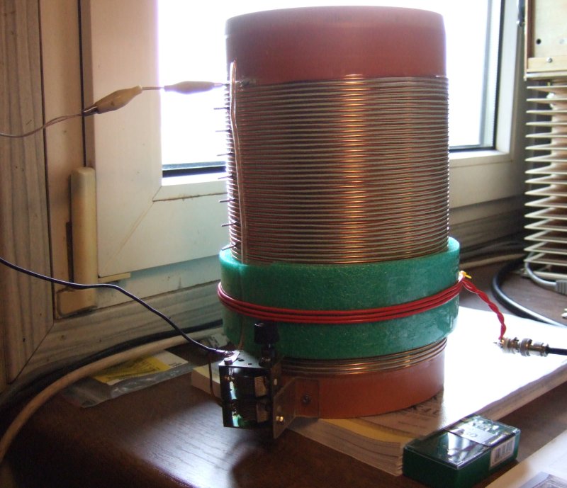
Primary coils (60 turns) and secondary coil (2..3 turns, with red plastic coated wire)
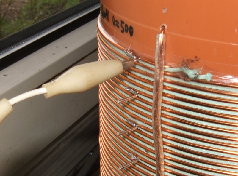
are separated by about 1 cm. For simplicity, foam plastic from an iso-mattress (sic!) was used. The original 'receive-only' setup consisted of a short wire, which was connected to the topmost tap of the primary coil (largest impedance). To connect longer wires without degrading the 'Q' (which helps to keep the strong MF broadcast signals away from the receiver), different taps were made on the primary coil. They will later be used to find the best impedance match for a longer transmit antenna.
With the above receive-setup, crossband contacts with various stations from the UK and Ireland on the 'old' band around 500 kHz were made.
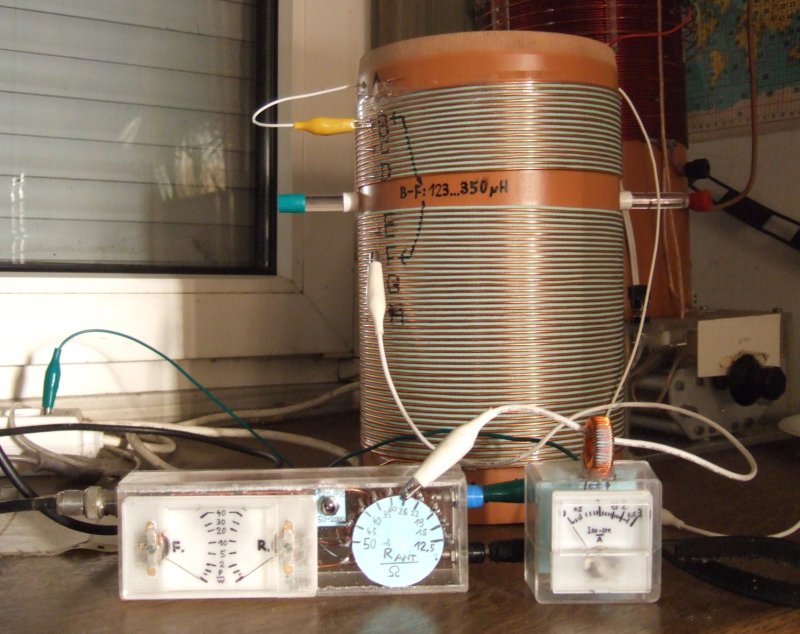
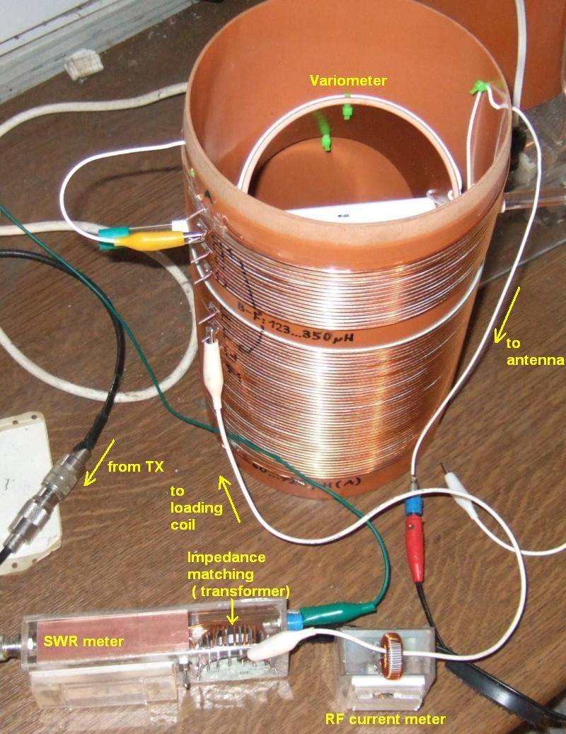
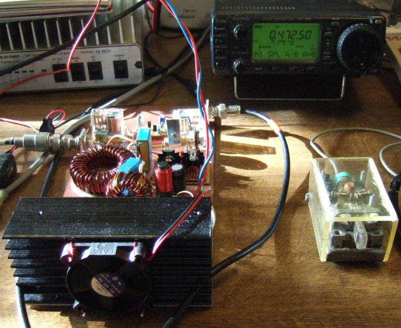
Transmission tests and antenna matchingIn June 2012, German radio amateurs were positively surprised by the authorities (Bundesnetzagentur, BNetzA) when the frequency range 472 to 479 kHz was allocated on a secondary, non-interference basis with a maximum ERP of 1 watt. On this occasion, a big thank you to everyone involved !The loading coil shown above was turned into a variometer (to make it suitable for transmission with a low power level), and a few homebrew accessories were added:
In the foreground, from left to right:
The variometer consists of the old loading coil wound on a plastic tube with 15 cm OD,
and a smaller inner tube with 11 cm diameter. The wire for the inner (rotatable) coil
is old 'Tensolite' wire (most likely Teflon covered, silver plated Litz wire).
The loading coil compensates the capacitive reactive part of the antenna impedance (-j * 1 kOhm here),
by connecting +j * 1 kOhm in series. The result is purely resistive, and consists of the ground loss,
environmental loss (trees), coil loss, and a tiny bit of radiation resistance (in this case, way below 1 Ohm).
The output tap on the 'impedance transformer' (integrated in the SWR meter housing) was set for 26 Ohms
to achieve the lowest possible SWR, thus with a 30 watt transmitter it should be possible to push 1 Ampere
into the antenna wire. It was.
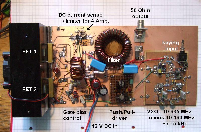
The transmitter used for the initial tests was built in a rush (before discovering that the old IC706 can be used as an exciter for 472 kHz):
An Icom IC706 as 'exciter' (in german: "Steuersender") on MF
By accident, it was found that the author's old IC706 would transmit around 472 kHz.
It's not sure which of the modifications in this radio's former life did the trick, but quite certain
it is just a matter of configuration (these "modifications" used to be on mods.dk or other sites).
Anyway, the external MF "power" amplifier will remove harmonics, so this less-than-ideal waveform is not a problem.
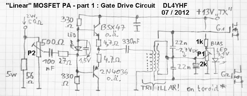
10 Vrms on 50 Ohms is approximately 2 Watts of RF, but voltage and 50 Ohm impedance are too large to drive the power MOSFET's gates directly.
The complementary push/pull driver was left unchanged. Note that the 22 nF capacitors parallel to the MOSFET gates
are not a typo: Together with the rather low inductivity of the step-down transformer (trifillar wound ferrite toroid),
they form a resonant tank (with low Q) near 475 kHz.
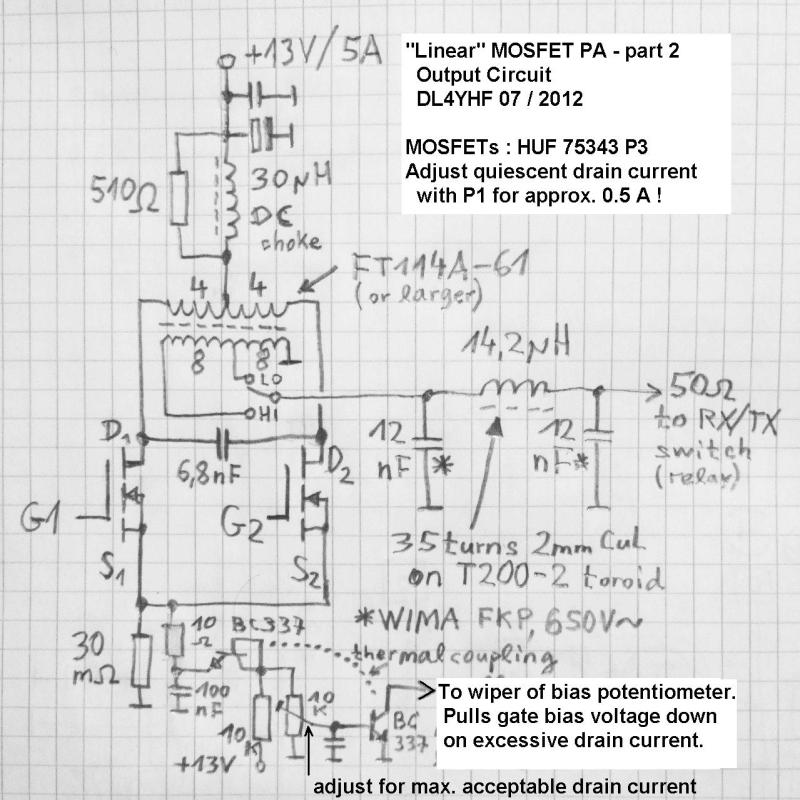
The output power could be increased with more secondary turns on the output transformer, if a larger ferrite toroid was used
(in the author's prototype, an FT114A-61 was used because nothing else was found in the junk box). Through the secondary
taps, the output power can be selected without sacrificing the PA's efficiency. When tested with 14 turns secondary,
the PA delivered 30 watts RF, and consumed 3 amperes DC input current. This was at the amplifier's clipping point,
i.e. more input drive didn't significantly increase the output power anymore. For CW, this is acceptable, and SSB isn't
an option on MF (even though it would be technically possible with this amplifier, when "moderately driven").
With a 'linear' power amplifier (in addition to a 'linear' exciter, such at the IC-706 in this case)
all kinds of soundcard-based modes are possible, including those with a non-constant RF envelope.
Sidenote: Similar effects can be seen on shortwave, when operators overdrive their transmitters
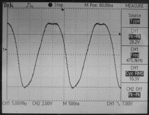
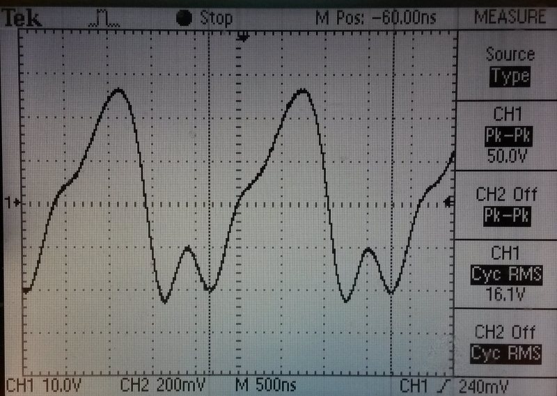
in PSK31, trying to squeeze 100 watts average power out of a 100-watt radio ;o) An Icom IC7100 as 'exciter' on MFWith an IC7100 feeding a series-tuned 'long' wire antenna (using the variometer shown here) on a friend's QTH, strange things happened: Even with perfect impedance- and resonance tuning for the operating frequency, the SWR indicated by the transceiver itself never dropped below "2.5" even at moderate output levels.An oscilloscope tapped at the 50 Ohm output directly at the transceiver showed the reason:
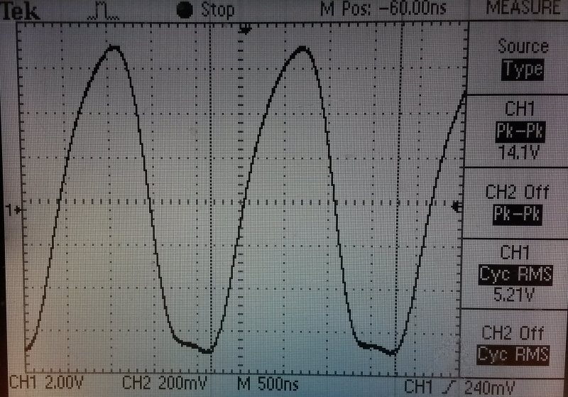
The bad SWR is a result of a missing 50 Ohm match for the harmonics, regardless of 'how good' the match was for the intended transmission on 472 kHz. This Icom shouldn't run 'barefoot' on the anntenna, and a linear power amplifier (to avoid key clicks) must equipped with an additional narrow-band filter before the push/pull driver. The IC7100 allows controlling the output power at MF in fine steps (see table further below). At the lowest power setting, the waveform 'approaches' a sinewave but still needs a lowpass before the external power amplifier:
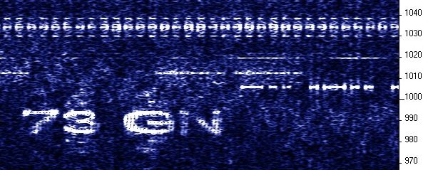
Initial activity on MF (starting in June 2012)
With the IC706 (HF transceiver), using 30 .. 40 W from the old tiny amplifier
shown in a previous chapter on this page, and 1.2 A antenna current, reception was reported through the
WSPR network from a number of receivers in western europe (DL, F, I, PA, ON, G, GM, EI).
Even during daylight conditions, the MF signal with an estimated ERP of 500 mW (which was later found to be much less (*) ) was copied
at GM4SLV in Shetland, over a 1000-kilometer distance.
In winter time, the ionospheric absorption drops faster, and 'DX' signals appear from the east before sunset. With a moderate ERP, and place not plagued by local QRM, contacts were made in relatively slow CW (but not QRSS) with Malta (9H) and Romania (YO). In January 2013, radio amateurs in other European countries got access to the 630 meter band, like the UK (requires an NoV) and the Netherlands. This will hopefully boost activity beyond 2013-01-01, when the first stations in PA, and one hour later G, GW, GM, and EI got 'on air' just a few minutes after their local midnight. 2014: Improved linear amplifier, with improved efficiency
When it became obvious that the ERP was 'much lower than expected', and some stations had difficulties
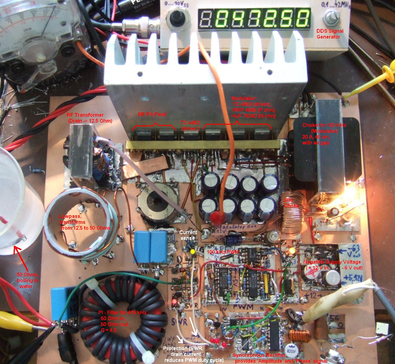
to copy DF0WD on MF, a new final amplifier was built. To use the existing '13.8 V, 20 A' power supply, a more efficient design
was required. The choice was that, instead of operating the MOSFETs in the 'linear' region (which resulted in a poor efficiency),
the RF power output stage should run in switching mode, and produce a maximum power of approx. 150 Watts;
ideally from a DC supply of not more than 15 A (at 13.8 V) to have some margin for the IC-706 (exciter) from the
station's '20 Ampere' power supply. With a DC input power of approx. 200 W, and an RF output of 150 W,
the design goal was "at least 75 %".
Details about the new PA (with switching-mode 'power modulator', put into service in January 2014) are in another document; see 'Switch-Mode Linear'.
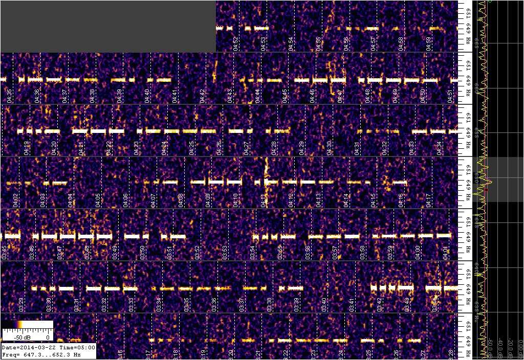
2014-03: Various reception tests, VO1NA in slow CW (QRSS)
... to be continued ... Ball Variometer (Kugelvariometer im Eigenbau)The ball variometer shown below was initially just a 'bad weather project', build partly for fun, and to get a fellow ham QRV on medium wave. The easier to build 'PVC pipe variometer' shown further above on this page has a limited tuning range, and it's difficult to switch the many taps on the loading coil remotely (when the variometer is located far away from the radio shack, under the roof, in the garden, on a mast, etc).
10 * 6 pF + 40 * 5 pF = 290 pF . Reactive part of the antenna impedance: Xc = 1 / ( 2 * pi * f * C ) = 1 / ( 2 * pi * 472 kHz * 290 pF) = 1162 Ohm This capacitive part must be compensated with an inductor ("loading coil"), connected in series with the antenna wire. At resonance, Xl = Xc; Xl = 2 * pi * f * L, thus: L = Xl / ( 2 * pi * f ) = 392 uH . Because the antenna may be shorter than 'initially hoped' (tree closer to the house than guesstimated..), the variometer needs some headroom (L), so the design goal was 500 instead of 392 uH. After playing around with online calculators for single-layered coils (especially this one by Serge Stroobrand, ON4AA), the inner coil should have a diameter of at least 120 millimeters, with 50 turns of 1-mm enabelled copper wire evenly distributed over the coil former's surface (which will be a sphere instead of a cylinder here, but let's ignore that for a moment). In the interest of a high Q, there must be some spacing between wires. You can try this out for a helical coil with the above coil designer:
For the inner sphere I used two wooden disks, produced with a simple scroll saw (Dekupiersäge). Each disk was slotted from the 'pole' to the center, slot width equal to the plywood thickness, to stick them together easily. 1.5 millimeter holes to hold the wire were drilled near the outer edge of the disks (see drawing further below). Then the wire was 'screwed' into the holes from a spool with the same diameter as on the sphere's equator, beginning near the equator (latitude 0°), and ending near the 'arctic circles' (latitude 66°). Wire loops closer to the poles don't add much inductance so omit them. Threading the wire through 4 holes for each turn is easy but time consuming. I wasn't very patient and used too much force for the prototype, resulting in a few kinks in the wire (nothing to worry about, as long as the wires don't touch): 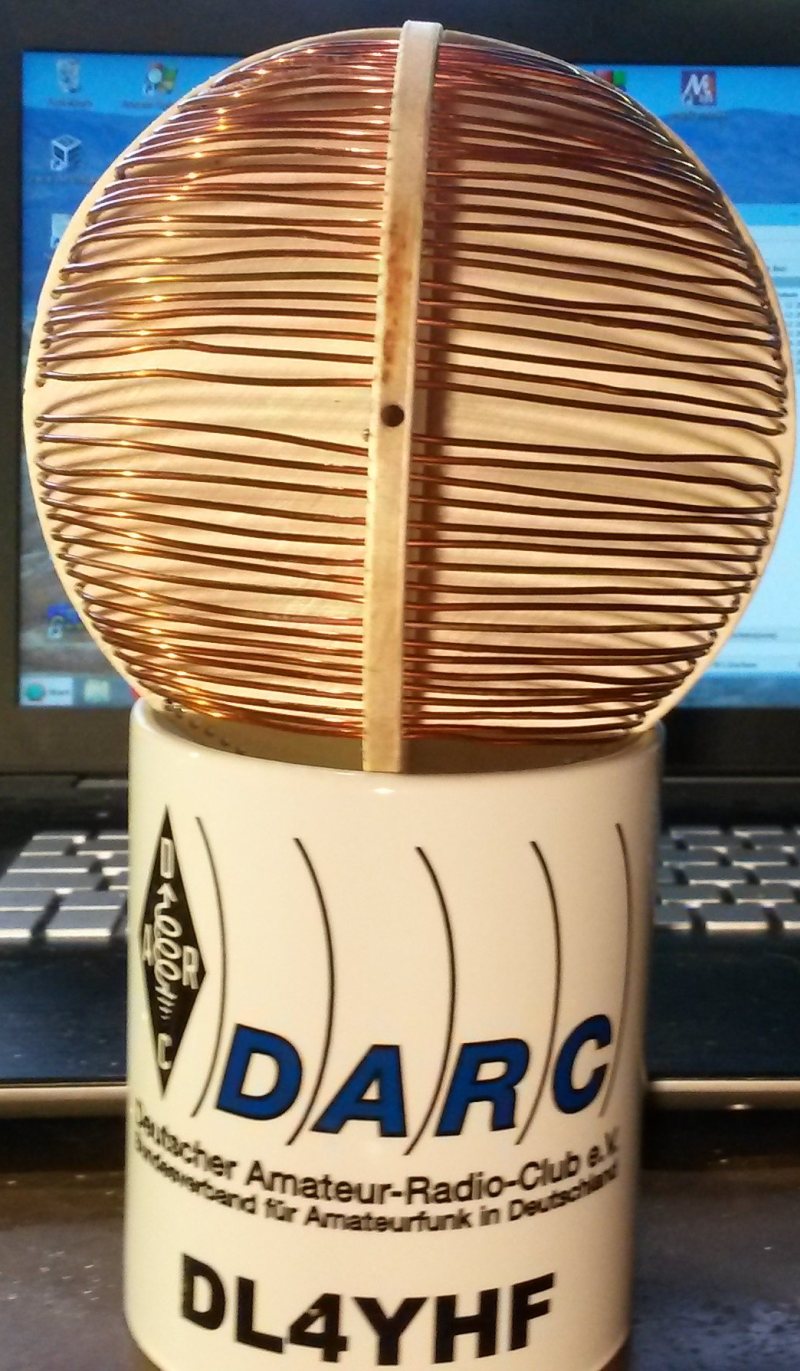
First prototype, almost ended up as decoration for a christmas tree. The outer coil is slightly larger than the inner, just large enough for 'production tolerances' and to withstand a few kilovolts - see suggestion for a 'slighly larger variometer' further below. Again, lots of holes with 1.5 mm diameter had to be drilled into the plywood plates to hold the wire (1 mm diameter). The outer cabinet consists of an upper and lower part: 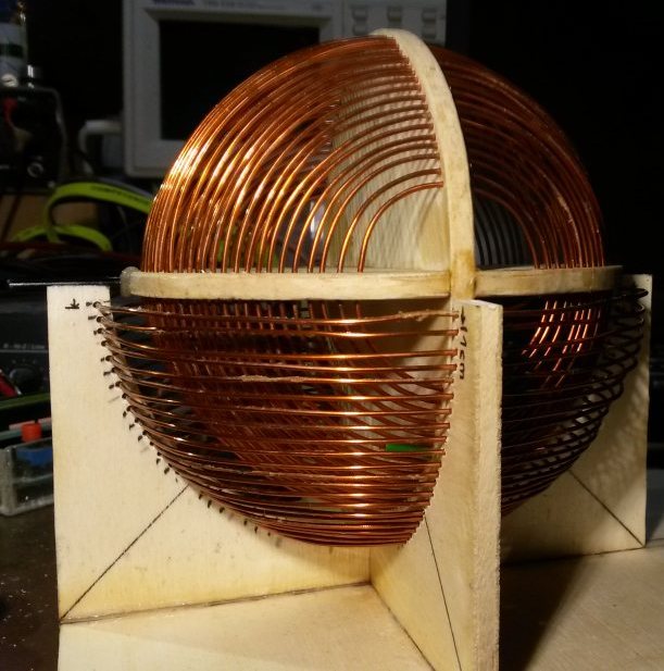
Measured result: Lmin = 45 uH (*) Lmax = 388 uH Rloss = 5.8 Ohm at 472 kHz (**), Q = 176 at Lmax (*) At the minimum position, the magnetic fields from both ball-shaped coils should cancel each other. Here, they don't (at least not completely) due to the unavoidable spacing between both layers. The 'Q' was measured indirectly by connecting a large Russian 300 pF capacitor (rated at 3.5 kV) in series with the coil, and measuring input voltage and current at resonance. The actual 'coil Q' may be a bit higher because there will be some loss caused by the capacitor itself, which is ignored here).
Lmin = 82 uH Lmax = 515 uH If I was to build another ball variometer for MF, I'd use a few more turns on both spheres, and a slighly larger disk diameter.. something like this: 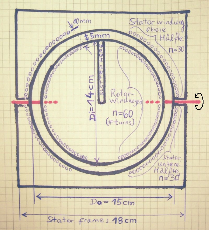
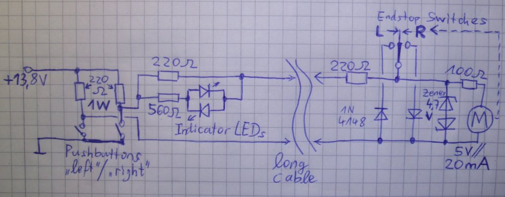
Inner sphere: 60 turns * 14 cm diameter * pi = 26.4 meters Outer sphere: 60 turns * 15.5 cm diameter * pi = 29.2 meters Total : Less than 55 meters of 1 mm enamelled copper wire, because only turns near the equator have those diameters. As already stated in the introduction, if you don't need an antenna tuning range of a few octaves, and the antenna impedance (reactive part) is known in advance, a simple 'tube' variometer with a large fixed part, and a small variable part, is easier to build than a ball variometer. Regardless if the variometer is a simple 'tube-' or a ball variometer, it often needs to be controlled remotely because the capacity between antenna and ground (earth) changes with weather, soil conductivity, etc. There may be some kilovolts(!) on the wire between the loading coil (variometer) and the antenna, so you don't want to run that wire from the shack to the roof or through the garden. At the end of the video on the begin of this chapter, you see a large wooden gear between the variometer and a very small gear motor (the type used in RC models). A DC gear motor by 'Faulhaber' only consumed 5 mA at 2 Volts (!) to rotate the inner coil at low speed, so a simple passive circuit was used to drive it remotely:
Links (medium wave related)DX cluster with filter for the 472 kHz band (OH8X DX Summit)DM4TR MF Grabber: 472-479 kHz live spectrogram by Thomas, DM4TR, in JO61DE DK7FC MF Grabber: by Stefan, DK7FC, in JN49IK Grabbers in Birmingham: A long-lasting service for LF and MF by Dave, G3YXM TF3HZ live spectrograms (covers a part of the 630 meter band) The Shetland Grabber: 472-479 kHz live spectrogram by John, GM4SLV (temporarily offline?) WSPR Spot Database for MF and LF ("old" interface but imo easier to use) The RSGB LF Group (at Yahoo), also used by MF operators GW3UEP's site devoted to 500 kHz CW with a variety of homebrew CW transmitters Operating Portable on Medium Wave by Finbar, EI0CF - Amateur Radio at it's best ! G4WGT Multi-Grabber page: now includes the new 630 meter band. Temporary 500 kHz (or 475 kHz) grabber by Rik, ON7YD WebSDR at the Universtiy of Twente; with gapless coverage from 0 to 29 MHz .
|
||||||||||
back to DL4YHF's main ham radio homepage
|