Hentenna for the 6m band
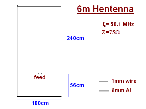
Dimensions

Simulation using mmana
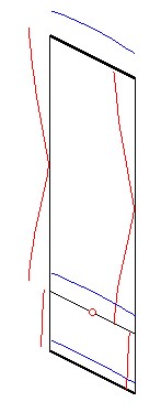
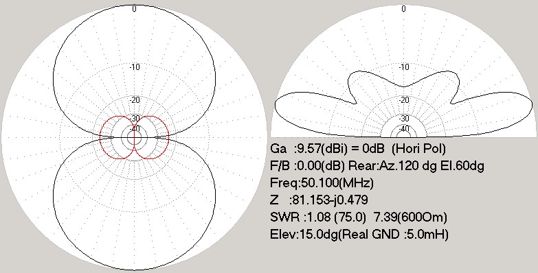
First image showing the current distribution on the aerial, the second
one the directional diagrams. The "real" ground settings were used,
with the Hentenna "placed" in a hight of about 5m.

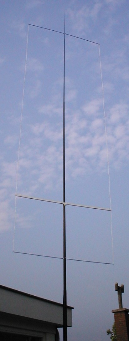
Normal and 3d photograph
This is what it finally looks like...
If you happen to own red/green glasses for
viewing 3d-images:
Hints & Experiences
The feeding section perfectly fits into a small (13x13mm²) 1m long
cable channel. The cable channel suffers from a couple of holes drilled
in it's sidewall in order to guide out the feeding leads. A luster
terminal is finally applied to connect the coax cable. In a former
version a bamboo pole was used; doesn't look as nice, but less work
to
be done...
You might practice some inventiveness in order to connect the 1mm
cables to the end of the aluminium poles... I squeezed the end of the
pole a little bit with pliers and cut a 4mm thread into the inner
surface of the Al pipe.
Used it as shown above. The aerial gave nice instantanious results
(beacons & Co.), even though that the band was pretty dead, I
managed to have some QSOs with reasonable results. My impression is,
that the Hentenna performs better than my commercial Al-pipe dipole.
Moreover it is easier to transport and/or store anyway.
The total costs were about €10.- w/o the feeding RG58 --- I known,
50Ohm cable to a 75Ohms aerial...


