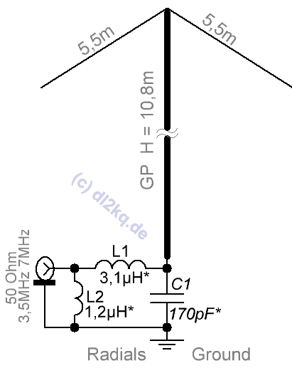
Figure 1. Antenna and matching
Quite a few dual-band verticals have been described in which a dual-band LC matching device matches the antenna impedance a 50 Ohm on both bands.
But they do have one drawback. On the lower band, the height of the vertical is at least λ/4. This practically rules out their use on the LF bands, where as a rule for design reasons the vertical is physically shortened on the lower band.
This article describes a dual-band 3.5/7 MHz vertical that is shortened in the 3.5 MHz band. In this band its height is only 0.128λ (physical 10.8 m).

A 10.7 m high telescopic mast stands on a 10 cm high insulator, and the insulator stands directly on the ground. The ground has the usual radials for both bands. As with any vertical antenna, the quality of this grounding determines the antenna gain and bandwidth. On top of the mast are two wire 5.5 m as capacitive loads at a 450 angle to the mast.
The dual-band matching unit has only three parts: one capacitor parallel to the insulator and a pair of small coils.
Model file 80_40.maa. The ground loss resistance is set to 15 ohms (first load), i.e. corresponding to a system of several radials lying on the ground or shallowly buried.
The antenna by band works as follows:
3,5 MHz
The antenna is shortened physically and electrically. The matching (as with any short verticals) is provided by a pair of coils: a small L2 coil parallel input and a large serial L2. Capacitor C1 in this range though influences, but a pair of coils copes with it.
The plot of the VSWR in this range is shown in Fig.2.

As with any other shortened vertical of this band, the bandwidth does not cover all allowed 300 kHz. But it quite overlaps the CW and digital parts of the 80 m band.
7 MHz
GP has an electrical ~0.38λ and therefore a high input impedance with an inductive component. An L1 C1 circuit is required to match it. The parallel coil L2 in this range works as a small RF choke.
The plot of the VSWR in this range is shown in Fig.3.

The whole range is overlapped, although with a good (less than 1.5) VSWR only 200 kHz.
At 1 kW input power (all currents and voltages are given for this power), C1 must be able to handle at least 1.5 kV voltage and 10 kVAr of power (for example, K15Y-1).
The same 1.5 kV voltage must be supported by the insulator. Since C1 is connected in parallel to the insulator, the design capacitance of the insulator can be very high. I.e. the insulator can be electric low-frequency. Or even of the "mast pipe" type inside an earthed support pipe, separated by a layer of plastic. Of course, the capacitance of C1 must be reduced by the constructive capacitance of the insulator.
The current in the coils reaches 7 A, in L2 - 4,5 A, accordingly it is necessary to choose the diameter of their wire.
It is done all the way down, at the base insulator (it must be good, the voltage on it will be high).
Sequence and methodology:
We start with the 3.5 MHz band. By tuning both coils (L1 - resonance frequency, L2 - VSWR at minimum) we achieve an exact match in the middle of the desired section.
7 MHz band. Without touching L2, the capacitor C1 and the coil L1 seeks the minimum VSW in the middle of the range of 7 MHz.
Back to the first point. And cyclically repeat steps. 1 and 2 until we get an accurate match in both bands..
The matching unit has a reserve for possible small deviations in the GP design. So in the file 80_40_1.maa shows a version with a different angle of inclination of the capacitive loads (they had to be shortened to 5.2 m each).
Debugging of the model for its design case is done by two-frequency MMANA-GAL optimisation of L1 L2 C1 values. If it does not work, you need to correct the height the GP and\or length of capacitive loads. But be careful: the two-frequency matching problem has a solution only for a radiator of certain dimensions, but not for any arbitrary size.
The antenna, described above, will provide good operation in the 3.5 and 7 MHz bands without switching. Tuning is not difficult and is done on the ground level. The antenna has a flush to the ground zenith pattern and good efficiency on both bands.