07.04.1999 Creation
Aus gegebenem Anlass weise ich darauf hin, daß diese Endstufe nichts mit der in diversen Auktionen angebotenen Endstufe zu tun hat und ich bezüglich der Anwendung keine Auskünfte gebe.
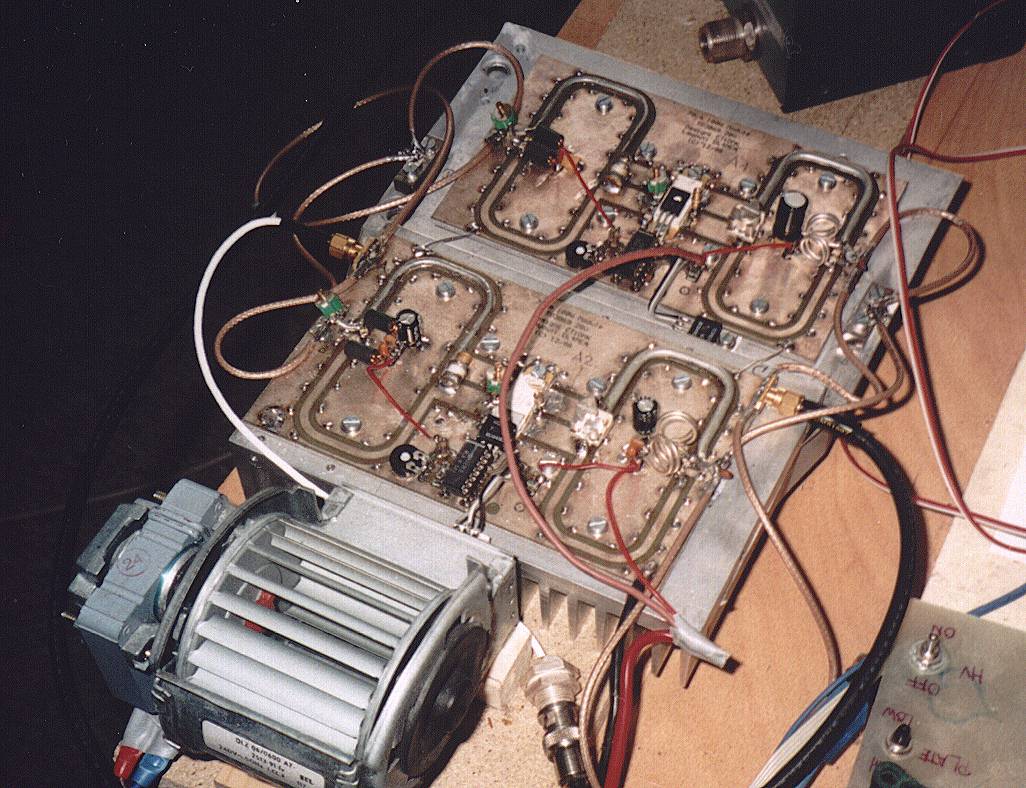
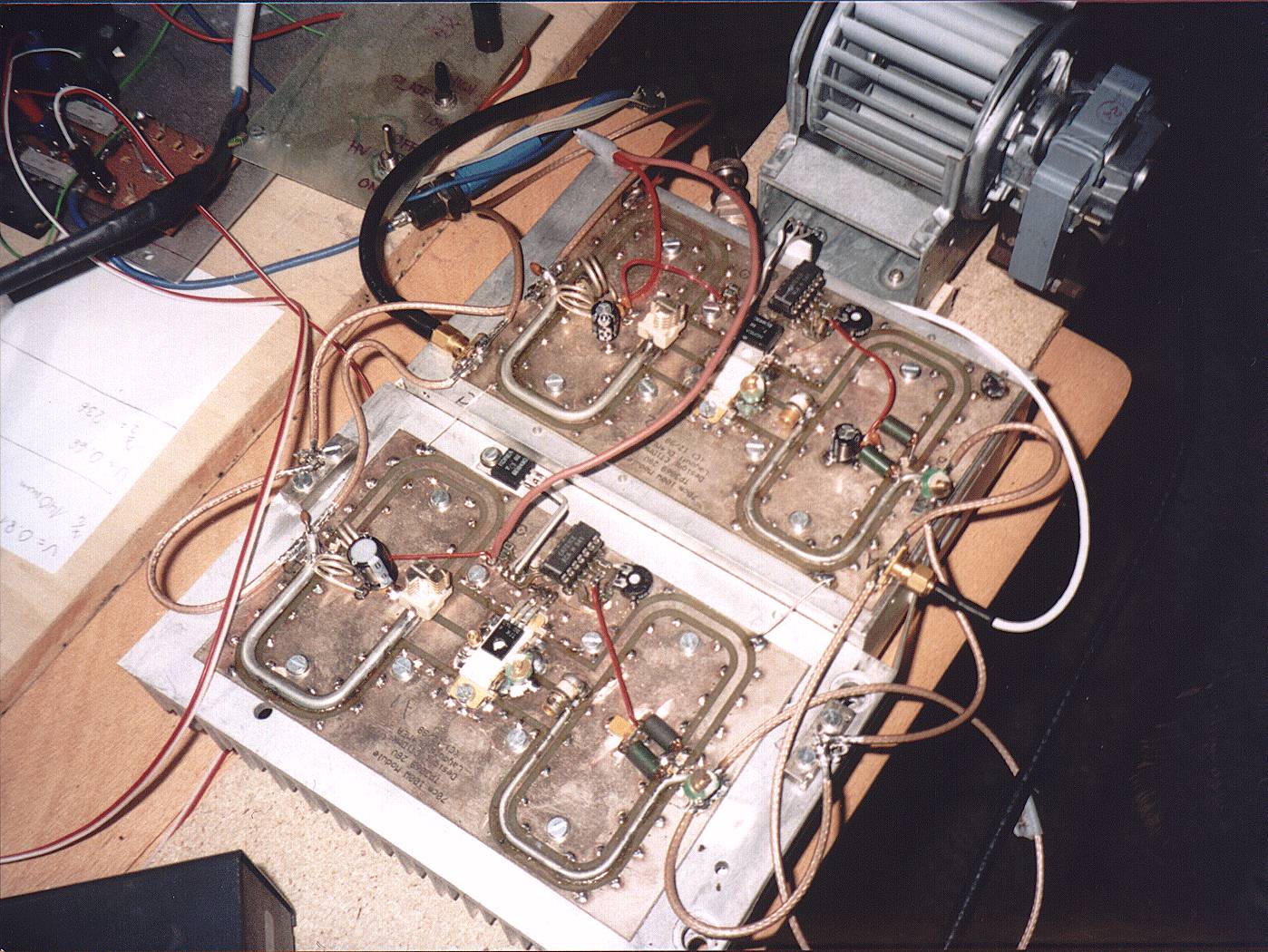
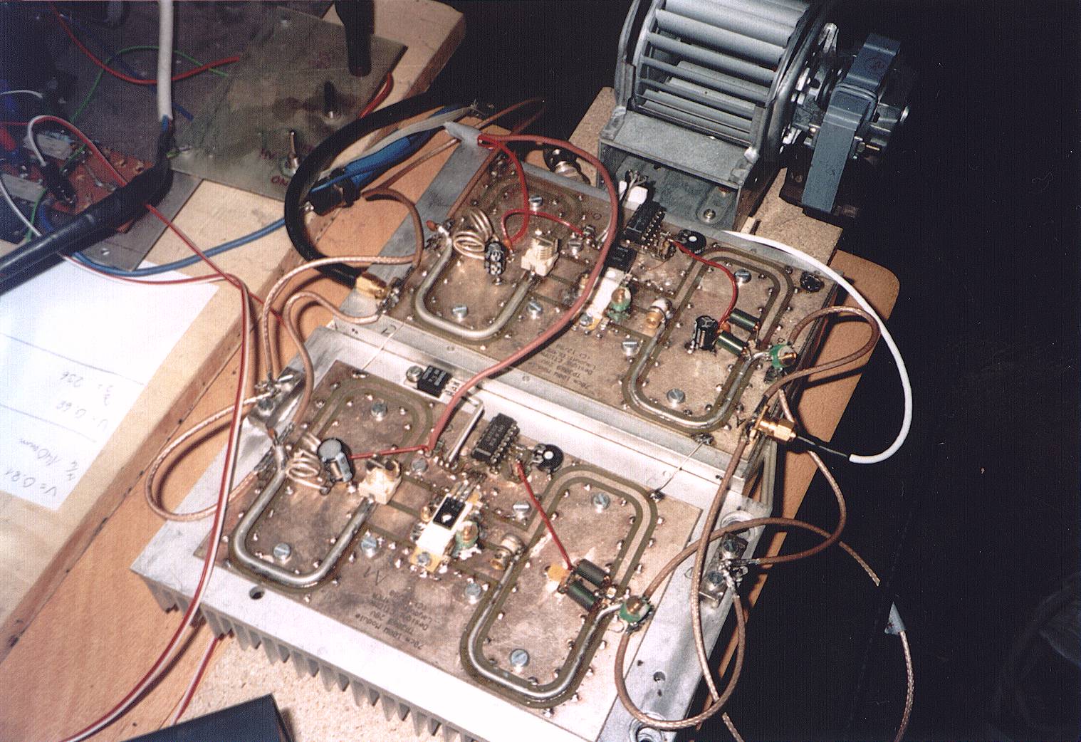
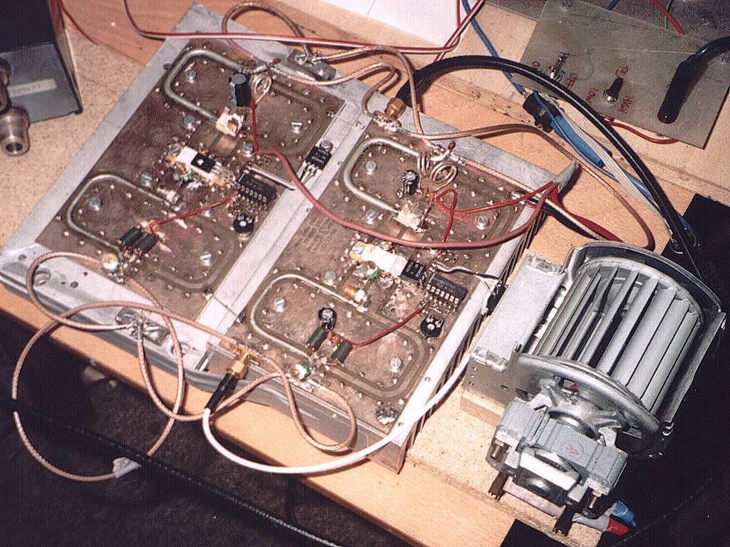
D: Der TP3069 ist ein für den GSM-Bereich um 900MHz entworfener bipolarer Gegentakt-Transistor. Ich erhielt einige davon und habe zusammen mit CT1DMK diesen Transistor in ein Design für 432MHz eingebracht, mit dem eine einzelne Stufe ca. 150W bei ca. 10dB Verstärkung bringt. Hier gezeigt ist die Kopplung von zwei Moduln mittels eines 1-1/2-Lambda-Kopplers um damit bis zu 300W Ausgangsleistung zu erreichen. Ich plane eine Endstufe mit vier TP3069 um unabhängig von meiner GS35b eine Endstufe zu haben, die keinen Lärm produziert und auch sofort nach Einschalten betriebsbereit ist.
Technische Daten (einzelne
Stufe):
| Betriebsspannung: | 26-28V |
| Stromaufnahme: | ca. 8-10A |
| Eingangsleistung: | 15W |
| Ausgangsleistung: | 150W |
| Ruhestrom: | 400mA (gesamter TP3069) |
Da es sich gezeigt hat daß der TP3069 sehr empfindlich auf die Ruhestromeinstellung reagiert habe ich dort etwas mehr Aufwand betrieben.
Um allen Fragen gleich vorzubeugen, ich habe keine Transistoren mehr übrig noch weiß ich eine Quelle oder sonstiges. Ich habe mich entschlossen dieses Design hier zu zeigen weil es sich sicher auch auf viele andere ähnliche GSM-Transistoren anwenden läßt und weil die hier gezeigte Anpassung mittels eines Lambda/2-Baluns in Amateurkreisen recht selten vorkommt. Leiterplatten habe ich auf Anfrage zur Verfügung.
E: The Motorola TP3069 is a push-pull
bipolar device designed for the 900MHz GSM band. I got several
from them and made it working on 432MHz togehter with the help of
CT1DMK. A single stage is capable of providing 150W output power
at around 10dB gain. Here you can see how two modules are coupled
using a 1-1/2-wavelength-coupler for a final power of 300W. I am
planning an amplifier using four TP3069 to be independent from my
GS35b amp not having the noise of the blowers and also to be
QRV simply after switching on.
Technische Daten (einzelne Stufe):
Technical data (single stage):
| Operating Voltage | 26-28V |
| Current: | ca. 8-10A |
| Input Power: | 15W |
| Output Power: | 150W |
| Idle Current: | 400mA (complete TP3069) |
I got the experience that the TP3069 is very sensible on the setting of bias voltage and idle current so I spent a little more effort into that.
To answer questions in advance: I
do not have any more TP3069 left over and do not know a source or
anything else. I decided to publish this amp here because it is
shurely usable for other GSM devices (or high power
push-pull devices for lower frequencies) and because the matching
using a WL/2 balun is not so well known in amateur radio.
If asked I have PCBs available.
Schematic:
Picture: Place Plan
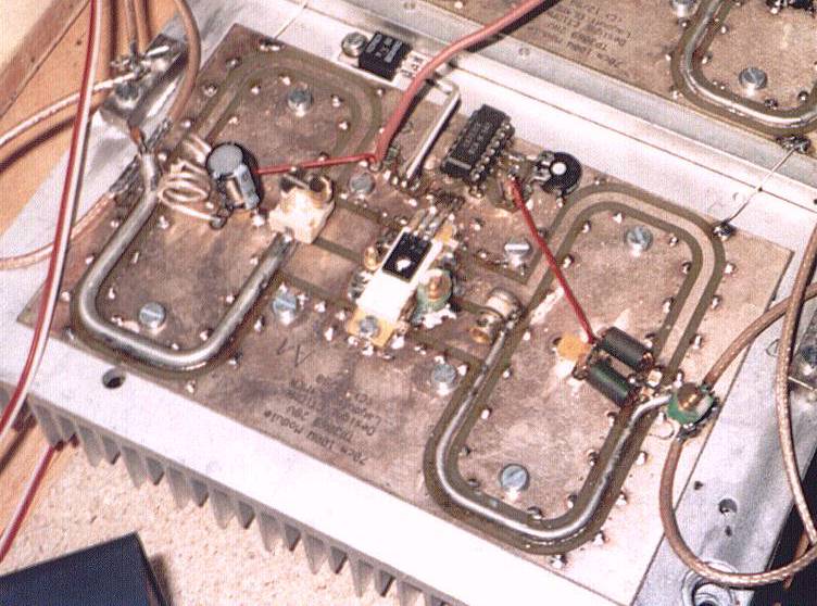 Placement of the rf components |
 Placeplan of the biasing circuit |
Pictures
 |
 |
 |
 |
![]() (C) by DL4MEA and CT1DMK
(C) by DL4MEA and CT1DMK