
Audio via "COM"- or UDP port (for Spectrum Lab)
Contents
- Introduction
- Configuring 'Audio via COM port'
- Frame synchronisation (for external ADC connected via serial port)
- Configuration examples
- Audio via UDP - Technical Details
- Audio via TCP - Technical Details
- Troubleshooting
Introduction
To connect external A/D conversion hardware without the need to write
an extra 'driver' for the PC, Spectrum Lab supports reading
'audio via the serial port' (aka 'COM port') in various formats.
Most of the formats are detected automatically because the
microcontroller (which drives the A/D converter)
embeds 'info headers' in the serial data stream, which SL uses
to detect the number of channels, bits per sample, sampling rate,
and possibly the precise (GPS-based) timestamp of the digitized samples.
For developers: The default streaming format is simple. More advanced
formats, originally used over UDP or TCP connections could be used
over the serial port, too (*).
Regardless of which format is used over the serial port, the serial data
format (e.g. "8-N-1"), the serial baudrate (e.g. 115200),
and the sample or packet format must be specified in the
'params' field. Slightly more advanced, packet-based formats allow
the external A/D converter to specify the number of channels,
the number of bits per sample, and the precise sampling rate
over the serial port itself (at least with the "PACK7" format).
More on that in the next chapter.
- Simply sending what was supposed to be sent via TCP/IP over
a serial interface ("COM port" under Windows, UART in a microcontroller)
turned out to be problematic, due to the missing packet / stream synchronisation,
and the almost-non-existing error detection (just a primitive "parity bit")
by the UART hardware.
Thus, since 2023-07, it is highly recommended not to use the
same header structures as for 'audio via TCP' or 'audio via UDP' over the serial port.
Instead, if possible in e.g. a microcontroller-driven A/D converter for the
serial port, use the Seven-Bit-Packet format
("PACK7") as shown later in this document.
For microcontroller firmware developers, there is even a reference
implementation available in plain "C", described and specified in a
separate document.
Configuring 'Audio via COM port'
Open SL's Audio Settings tab. On the panel titled 'Input Device / Pipe / Driver', expand the list of input audio devices. It usually contains several normal audio devices (soundcards, USB audio devices, possibly ASIO), a few specialized drivers for SDR, and -if such interfaces exist on your system- a few COM ports. Under Windows, COM ports are listed by their numbers only, e.g. 'COM1', 'COM2' (which used to be the onboard RS-232 interface in the good old days), 'COM3 (which is typically used for the first USB-to-RS232-adapter enumerated by Windows, etc etc.Step 1 : Select the "COM port" (serial port)
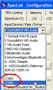
Audio-via-COM, step 1 : select the COM port in SL's "Input Device" combo.
Depending on the Windows version, certain COM ports may have a 'friendly'
name appended, e.g. "COM11 (USB Serial Port)" instead of only "COM11".
The port may already be occupied by Spectrum Lab itself (when already selected, and audio processing started.
Otherwise (e.g. "COM8 (occupied)") the serial port may be already opened by another application.
-
(the "occupied" indicator described above was removed, because some crappy Bluetooth driver
seriously slowed down the COM port enumeration process, thus SL now cannot check in advance if
a COM port is occupied anymore)
Step 2 : Define the data format (in the "params:" field)
Besides the COM (or UDP-, or TCP-) port number, SL needs to know the format of the digitized samples received by, or sent to the port. That additional information must be provided in the 'params' field right below the list of 'Input Devices / Streams / Drivers'.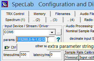
Audio-via-COM, step 2 : describe serial port settings in the "params" field
Flow control is not supported, and not required on today's computers (which are always fast enough to receive a few hundred kilobits per second without a receive buffer overflow). Speeds supported by modern USB <-> RS-232 adapters are 115200, 230400, 460800, and a few even worked at 921600 bits/second (=8*115200).
For example, to 'stream' 11025 samples/second with two channels and 16 bit resolution, plus an overhead of at least 3 bits per byte for start-, stopbit, and inter-frame gap, the required serial bitrate would be 11025*2*16*(11/8) = 485100, thus the next higher 'standard' bitrate would be 921600 bits/second.
For Audio-via-UDP or TCP, the baudrate and 'serial data format' are meaningless, and should be omitted. UDP and TCP only need a specification of sample format. Only Audio-via-COM expects the sample format after the serial data format, separated by comma as shown in the screenshot above ("115200,8-N-1,IQ12").
The remaining (and usually mandatory) part in the 'params' field describes the (usually 'simple') sample format, e.g. S16,SYNC = Signed 16-bit integer with occasionally injected 'SYNC' pattern.
The table below shows all 'simple' sample formats supported by Spectrum Lab at the time of this writing (2023-08):
| format-token | explanation |
| U8 | each sample is an 8-bit unsigned integer (0..254; value 255 should be reserved as sync pattern) |
| S8 | each sample is an 8-bit signed integer (+/-127; -128 is reserved as sync pattern) |
| U16 | each sample is a 16-bit unsigned integer (0..65535), little endian (least significant byte first) |
| S16 | each sample is a 16-bit signed integer, little endian (+/-32767; -32768 is reserved as sync pattern) |
| U16_BE | each sample is a 16-bit unsigned integer (0..65535), big endian (most significant byte first) |
| S16_BE | each sample is a 16-bit signed integer (+/-32767), big endian |
| U24 | each sample is a 24-bit unsigned integer (0..16777215), little endian |
| S24 | each sample is a 24-bit signed integer (+/-8388607), little endian |
| U24_BE | each sample is a 24-bit unsigned integer (0..16777215), big endian |
| S24_BE | each sample is a 24-bit signed integer (+/-8388607), big endian |
| U32 | each sample is a 32-bit unsigned integer (0..4294967295), little endian |
| S32 | each sample is a 32-bit signed integer (+/-2147483647), little endian |
| U32_BE | each sample is a 32-bit unsigned integer (0..4294967295), big endian |
| S32_BE | each sample is a 32-bit signed integer (+/-2147483647), big endian |
| IQ12 | DL4YHF's 12-bit I+Q sample format for PIC12F675, described below |
| GPSDO3 | 3- or 5-byte frames from DL4YHF's PIC-based GPSDO, Version 1 |
| PACK7 | Sample points are wrapped in
Seven-Bit Packets as explained later. Use for 'new designs'. This 'packet-based' format can transport most of the data types listed above, without the user (operator) having to know the details - thus highly recommended. |
If the number of channels (in each sample point) isn't implicitly defined by the sample format (for example, "IQ12" implies that each sample point consists of two values digitized at the same time: One for 'I', one for 'Q'), the number of channels must be appended to the format specifier, again separated by another comma. See examples in a later chapter.
The same (explained above for the input device) can also be used for the output device: Instead of a soundcard (or similar 'audio' device), select a COM port from the list, or manually enter the pseudo-URL of a UDP port in SL's Output Device / Stream / Driver combo, and define the sample format in the 'params:' field (there are two such fields, one for the input device, and one for the output device). Both the sender and the receiver(s) must use the same sample format, and the same number of channels. If both are different instances of Spectrum Lab, this is easily achived by using the same 'params:' string on both ends.
See also: Sending Audio via UDP without replacing the 'local audio output' (e.g. soundcard), in other words: Sending audio as 'Audio via UDP' in parallel to 'output to a local audio device').
Frame synchronisation (for external ADC connected via serial port)
Since the microcontroller usually starts transmitting at an arbitrary time, and because single bytes can always get lost 'on the wire' (especially if the 'wire' is a simple UHF ASK/FSK radio link), the receiver needs some sort of frame synchronisation (unless the stream consists of a single channel, with a single byte per sample). This can be achieved either by reserving a certain bit pattern which does not occurr in the 'normal' digitized data, or (preferred method, implemented 2023) using a 'packet' oriented protcol for the serial port, where bit seven (the most significant bit) in each byte sent of the serial port is sacrificed for a reliable communication (it allows the receiver to recover quickly after any error, either single-bit or multi-bit errors). Both of these methods have their pros and cons, explained in the next two subchapters.Old method (pre-2023) : 'SYNC pattern' (0x80, 0x8000, 0x800000, ..)
For signed integer values, a suitable bit pattern is the most negative number N (which the sender can easily replace by N+1, in the unlikely case that 'N' occurs in a digitized sample). No sync pattern is required is in streams with only 8-bit samples (format U8 or S8), and one channel.'SYNC' is also not required -or even harmful- for 'packet'-based formats like PACK7 - see next chapter.
For 16-bit signed integers (S16),
the sync pattern is 0x8000 (hex). The sender (microcontroller) must replace any sample value 0x8000 (= -32768 decimal) with the next negative number, which is 0x8001 (= -32767 decimal). A similar pattern is also used to mark any 'header' in a non-compressed audio stream via TCP/IP.
For 16-bit unsigned integers (U16),
the sync pattern is 0xFFFF (hex). The sender (microcontroller) must replace any sample value of 0xFFFF ('largest possible 16-bit value) by 0xFFFE (= 65534 decimal), which doesn't hurt much because the ADC's clipping point must be avoided (with some 'headroom') anyway.
For 24-bit signed integers (S24), the sync pattern is 0x800000 (hex).
For 24-bit unsigned integers (U24), the sync pattern is 0xFFFFFF (hex).
For 32-bit signed integers (S32), the sync pattern is 0x80000000 (hex).
For 32-bit unsigned integers (U32), the sync pattern is 0xFFFFFFFF (hex).
As for the integer sample values, the SYNC PATTERN is subject to endianness. All of the above formats have been tested with Little Endian only (aka 'Intel' byte order, least significant byte first).
The sender only needs to insert the 'sync pattern' occasionally (once every few hundred milliseconds). If it starts sending before launching Spectrum Lab, SL may receive garbage for a few hundred milliseconds because it doesn't know to which part of the frame the first received byte belongs. After recognizing the first sync pattern, the received samples will be properly reassembled, and the 'garbage' (usually a strong noise) disappears.
- SYNC : Transmitter occasionally inserts the Sync-pattern between sample points
- If the sender uses frame synchronisation (as explained above), append the string ',SYNC' (without quotes) after the format-token
in SL's 'Params'-field as shown in the previous chapter.
SL will then discard all received bytes until the first successfull reception of the complete sync pattern, and automatically remove the sync pattern from the input samples.
- SYNCS : Transmitter always inserts the Sync-pattern between two sample points (multiple channels sampled simultaneously)
- Almost identical to the SYNC option. The main difference is
on transmit: While SYNC only emits the sync-pattern once for an entire
block of samples (with the number of samples per block depending on the sampling rate),
SYNCS will emit the sync-pattern before every sample-point.
On receive, this option allows recognizing 'garbage' immediately, at the expense of the extra overhead, and if the sync pattern appears in the 'payload' (digital samples) by coincidence, it will not be flagged as an error.
     Byte index : |   0  |   1  |   2  |   3  |   4  |   5  |   6  |   7  |  8 ..
     -------------+------+------+------+------+------+------+------+------+---...
     Data byte    | 0x00 | 0x80 |Ch1_lo|Ch1_hi|Ch2_lo|Ch2_hi| 0x00 | 0x80 |
                  |<----SYNC--->|  Channel 1  |  Channel 2  |<-next SYNC->|

                  |<----- six bytes per "sample point" ---->|
                  '-----------------------------------------'
Newer method (since 2023) : 'Seven-Bit Packets' for audio- and other packets
This is the preferred method for microcontrollers with 'a bit more punch' than the ancient 8-bit PICs. It sacrifices the most significant bit in each 8-bit "frame" sent over the serial port to reliably detect the begin of a packet. For the tech-minded reader (and authors of a microcontroller firmware to connect an external A/D converter to Spectrum Lab via the serial port, or via USB / "VCP" (Virtual COM Port): Details about the packet format, packet types, etc are in an extra file (Seven_Bit_Packets_for_the_serial_port.htm).The format-token for data acquisition systems using this format (in fact any of the sample formats specified in the document linked above) is "PACK7". The microcontroller firmware (that 'wraps' samples from the A/D converter into packets) is supposed to report the sample format periodically, so there's no need for the user to specify the data type, number of bits per single sample, number of channels per sample point, and the precise sampling rate manually. If all works as planned, the first AUDIO_SAMPLE_FORMAT-packet will arrive a few seconds after Spectrum Lab has started, and opened the serial port, because any 'junk' (arriving when the port was opened just when there was 'traffic' on the RXD line) can be reliably skipped by the packet decoder, as long as there is a gap of at least eight bit-times between two packets. For that reason, the 'PACK7' format does not require the 'SYNC' option.
Configuration examples
This chapter contains a few examples for configuring Spectrum Lab to receive or send audio streams, over serial ports ("COM ports") or via UDP (LAN, WLAN). In any case (and in contrast to 'web audio streams'), samples are usually not compressed, and the sample formats are simple enough for implementation in almost and microcontroller (firmware for a uC-driven A/D converter on a serial port, USB/VCP, or UDP).Configuration examples for external A/D converters connected via serial port
With DL4YHF's old PIC based A/D converter for the serial port, each sample point (with two channels) consists of four bytes. The first byte in each sample point (aka 'frame' in the PIC firmware description) is the header byte. It usually contains 0xFF (255 decimal) which looks like a long 'stop bit' to the receiving UART, and is used for synchronisation purposes. The second byte in each frame contains the eight least significant digits of the 'I'-channel. The third byte contains the eight least significant bits of the 'Q'-channel. The fourth byte in each frame contains the four most significant digits of the 'I'-channel in bits 3..0, and the four most significant bits of the 'Q'-channel in bits 7..4 .The PIC sends those four-byte-frames with 115200 bits per second, 8 bits per UART-frame, no parity, one stop bit. Thus, the complete format description entered in the 'params' field would be:
params: 115200,8-N-1,IQ12
(with baudrate,serial data format,sample frame format)
In this special case (PIC-based ADC with serial interface), the ADC doesn't report its own sampling rate, so the 'Nominal Sample Rate' field in SL's Audio Settings must be set to that value.
Otherwise (with a wrong sampling rate) the frequencies displayed on SL's main frequency scale would be wrong.
For example, the PIC-based serial ADC mentioned above delivers 2500 I/Q samples per second, thus the displayable baseband frequency range is -1250 Hz ... +1250 Hz.
This may be different for other 'external' A/D-converters on the serial port !
Example for a serial stream with 9600 baud, 16 bits per sample (signed integer), single channel, sync pattern 0x8000:
params: 9600,8-N-1,S16,SYNC,1
(with baudrate,serial data format,sample frame format with the old 'sync' option, and number of channels in the stream)
Example for a serial stream with 9600 baud, 16 bits per sample (signed integer), single channel, sync pattern 0x8000:
params: 9600,8-N-1,S16,SYNC,1
(with baudrate,serial data format,sample frame format with the old 'sync' option, and number of channels in the stream)
Example for a serial stream with 115200 baud, 24 bits per sample (signed integer), two channels, sync pattern 0x8000:
params: 115200,8-N-1,S24,SYNC,2
- (with baudrate,serial data format,sample frame format
with the old 'sync' option, and number of channels in the stream.
At this low baudrate, only usable for low sampling rates, e.g. 1000 sample points per second).
Finally, an example for the highly recommended PACK7 format:
params: 921600,8-N-1,PACK7
(with a high baudrate of 8*115200 baud, supported by many USB<->RS-232 adapters or 'VCP',
8 data bits, no parity, one stopbit, and the highly recommended 'PACK7' format).
A stoneage FTDI "USB Serial Port" (adapter branded "DeLOCK") operated at this speed,
and even "Windows 10" listed this baudrate in the 'System Control' / Device Manager.
Configuration examples for audio via UDP
As already mentioned in the introduction, the same formats as originally only used for 'Audio via COM port' can also be used to send / receive simple, non-compressed audio via UDP (User Datagram Protocol), i.e. via LAN or (if sufficiently reliable without 'lost packets') via WLAN / Wi-Fi.As an example, let Spectrum Lab send its output via UDP to a certain port, opened by another application on the same PC ("localhost" alias IPv4 adddress 127.0.0.1), using the following pseudo-URL:
udp:\\localhost:6999 (e.g. in SL's Output Device / Stream / Driver field)
The sample format (specified in the 'params:' field, here of course without a serial baudrate, etc) uses exactly the same same format as for the serial port, because under the hood, the encoder/decoder is the same software module for 'Audio-via-COM' and 'Audio-via-UDP'. Thus, for the VLC player test, set 'params:' to:
S16 (i.e. Signed 16-bit integer in Little Endian format)
A test to play 'raw audio' via UDP with VLC player failed for obscure reasons, but the command line driven FFPLAY' (for windows: ffplay.exe, part of the ffmpeg suite of audio/video conversion tools) worked out of the box on the very first instance, flawlessly even at 48 kSamples/second, with the following command line:
ffplay.exe -nodisp -v quiet -stats -ac 2 -ar 48000 -analyzeduration 0 -probesize 32 -f s16le -i udp://127.0.0.1:6999
Of course you can stream Seven Bit Packets over UDP too (even though the packet format was intended for use over serial ports), but neither FFPLAYER nor VLC player will understand them.
Audio via UDP - Technical Details
This not only works between multiple instances running on the same PC (via "localhost"), but also between multiple PCs in the same network (with different IP addresses of course).The UDP-based method used for this purpose is utterly simple (it's just "fire-and-forget", using only the 'sendto()' function, but no fancy acknowleding of datagrams, and no error detection and automatic retransmission).
Thus, this method only works reliably in a local network, but doesn't work well 'over the internet' (lacking any protocol on top of UDP, like automatic retransmission if a packet gets lost on the way).
The simple UDP streaming as implemented here is not a client / server protocol. Instead, URLs (or pseudo-URLs like "udp://localhost:6999") of any receiver in the audio sending instance must be entered manually, so the 'transmitter' (to use another radio analogy) knows to which IP addresses and ports the audio shall be sent to. Multicast ("broadcasting") into the entire local network isn't planned, to avoid unnecessary network traffic.
Unless 'Audio via UDP' shall replace the normal (local) output device, its transmission is enabled in addition to the normal output device on the 'AD/DA Server' tab in SL's Configuration dialog:

Reduced screenshot of the 'AD/DA Server' tab,
with the Audio-via-UDP settings for the sending side.
(at the moment, 2023-08, audio-via-UDP can only be sent
to one or multiple destinations by entering the pseudo-URL
in Spectrum Lab's output device field).
In the example shown above, the audio signal is sent to the machine with pseudo-URL
udp://localhost:6999
The "localhost" is a dummy hostname, representing IP(v4) address 127.0.0.1.
This basically means the packet (UDP datagram) doesn't really travel over Ethernet or WLAN
- instead, it's only sent from one UDP port to another on the same machine.
In case of doubt, you can use the netstat command
as explained in the troubleshooting chapter to check if the planned UDP port
is still available on the local machine ("localhost"), or the remote machine
that shall receive the audio stream via UDP.
In most cases, the receiver of these unofficial 'Audio-via-UDP' messages
will be another instance of Spectrum Lab. That instance must be configured
to use UDP (as input) instead of the soundcard (etc).
This is achieved by entering a pseudo-URL of the 'sending' PC
(including the same UDP port), but possibly a different IP(v4) address
unless the sender is "localhost").
For a start, assume the UDP-sender and -receiver both run on the same machine,
so don't bother with numeric IP addresses or real hostnames.
Enter "udp://localhost:6999" in the 'Send audio via UDP to ..' field of the sending instance,
and "udp://localhost:6999" also in the 'Input Device / Stream / Driver' field
on the 'Audio I/O' tab in SL's Configuration dialog of the receiving instance.
For Audio-via-UDP, the sample format, number of channels, etc
must be specified in the 'Params:' field (right below the field
with the pseudo URL), with the same token as for other 'simple'
audio sample formats.
Audio via TCP - Technical Details
The option to send or receive the same 'simple' sample formats as previously only used for the serial port ("Audio via COM") was added shortly after "Audio via UDP" - after discovering, that even in a local network, a few of UDP frames may get lost on the way. This was a show-stopper for simple microcontroller-based ADC applications without a full-grown TCP/IP protocol stack, because (in contast to the super simple, connectionless, but unreliable "sendto()" / "receivefrom()" model in UDP), TCP/IP is a connection-based protocol, slower, but reliable. Thus it depends on the application if the occasional loss of samples (usually a block with a few hundred sample points) can be tolerated or not. It an occasional loss of samples cannot be tolerated, and latencydoesn't matter, use "Audio via TCP" in your local network.The next subchapter explains how the 'simple' "Audio-via-TCP" is implemented in Spectrum Lab.
"Audio via TCP" Client / Server model
In Spectrum Lab, if the 'Input Device' (name) begins with "tcp://", and the "params:" field (right below) contains one of the 'simple' sample formats listed here (same for Audio-via-COM, Audio-via-UDP, and Audio-via-TCP), where (usually) a server listens on a well-known port forTroubleshooting
Testing audio-via-COM/UDP/TCP with Spectrum Lab itself
Since 2023-08, Spectrum Lab also supports sending most of the formats listed further above to a serial port. This was initially used for testing the 'fitness' of several USB<->RS-232 adapters for this purpose, especially at higher baudrates for higher audio sampling rates, using the PACK7 format.To send an audio signal (generated by SL) to a serial port, instead of sending it to a soundcard, replace the name of the Output Device / Stream / Driver by the "COM port name" (e.g. COM11 if Windows decided to assign that number to your USB-to-serial-port-adapter today). Then, fill out the "params:" field directly below the 'Output Device' combo list as explained here ("define the data format") e.g. for the to-be-tested 'PACK7' format:
921600,8-N-1,PACK7
Note: Unfortunately, Windows only allows one application to open a particular serial port. Thus, for the sender, use one serial port, and for the receiver, use another. Alternatively, with only one serial port and one instance of Spectrum Lab 'occupying' that port, use the same COM port as input- and output-device. This works because since 2023-08, Spectrum Lab is smart enough to open the serial port only once when e.g "COM11" is used as both, input device and output device.
Then, with the test signal generator 'driving the output' with a clean sinewave, and the spectrum analyser connected to the input, corrupted samples or 'lost packets' will be easily spotted on the waterfall or spectrum display.
Recording 'raw' in- or output as binary files
When suspecting 'lost packets' or 'lost bytes' (which happened more than once, especially over certain serial ports), or Spectrum Lab occasionally reports 'garbage' received from the input device (displayed in the "Debugging" window / "Misc" tab ), consider logging the 'raw input' (received from the input device, e.g. an external ADC), or the 'raw output' (sent to the output devices, e.g. an external DAC) as explained below:- Open SL's 'Configuration and Display Control' window
- Switch to the 'Filenames' tab
- In the line with 'Input Stream Log', provide a filename of your choice,
and check '☑ active'
(In older versions, this feature only applied to 'web streams' for input. Since V2.99 b10, logging also works for 'Audio-via-COM' as well as for 'Audio-via-UDP' and 'Audio-via-TCP'. Instead of e.g "xyz.ogg" as file extension, use a filename like "audio_via_com_log.bin" because the result will not be supported by any audio player - it's just "binary".) - Click 'Apply' to make the new settings (filename and enable/disable status) work.
- If you don't need the 'input stream log' feature anymore, remember to turn it off, because it may quickly fill your hardddisk, or (even worse) a solid state disk.
Thus it's not intended as a replacement for the 'Wave' Audio Recorder, but as an aid for development of microcontroller firmware or similar.
If the decoder (binary parser) for received data detects errors in the data (e.g. bytes were discarded as "garbage" due to a misplaced SYNC pattern), the eight most recent error positions within the logfile are displayed as hexadecimal byte-offsets in the Debugging Display / 'Misc' tab. In the following example, one of the reported error positions was looked up in the binary logfile (using a 'hex' file viewer, like the one integrated in Total Commander). At the indicated position in the binary log, there was indeed a misplaced SYNC pattern (a bug later fixed in the sender, by more carefully checking multi-channel sample points for 'ACD noise' looking like a SYNC pattern. In this case, the high byte of the first channel, value 0x00, and the low byte of the next channel, value 0x80, together formed the 16-bit SYNC pattern. This can be avoided by e.g. incrementing or decrementing a 16-bit sample value by one. By the way, this is one of the reasons why the 'SYNC' pattern should be replaced by e.g. 'PACK7' wherever possible):
Log: 807 kByte written to logfiles\audio_via_com_log.bin.
      Errors logged at 0x0009C4E2,0x0009C4E5,0x000BBFCA,0x000BBFCD,0x000C56A8,0x000C56AB,0x000C9110,0x000C9113.
                                         ,---|________|
000BBFC0: D5 05 00 80 5F 0C 5E 0C 00 80 80 00 80 00 00 80  (hex address looked up in the binary logfile)
       [+  0  1  2  3  4  5  6  7  8  9  A  B  C  D  E  F]
                |___| |__data___| |___|    |___|
              good SYNC         good SYNC  bad SYNC (unintended, here should be DATA, not the SYNC pattern)
                      |___| |___|       |___| |___|
                       Ch1   Ch2         Ch1   Ch2
                      Lo Hi Lo Hi       Lo Hi Lo Hi
Testing audio-via-COM-port with a Python script (ultimately deprecated)
To test interfacing audio-via-COM-port without a microcontroller, you can emulate two COM ports on a single machine using com0com (a 'Null-modem emulator that can create a simple pair of COM ports on your PC). In June 2018, the author used com0com V3.0.0.0, available from sourceforge with a signed driver. The name of the downloaded file was "com0com-3.0.0.0-i386-and-x64-signed.zip", and with a bit of luck you can find it somewhere (beware, there's a confusing number of versions floating around, some without a signed driver which caused a lot of headache. So make sure you pick the right one).Next, pick a serial port library for your favourite Python flavour. For the simple example presented below, I used pySerial. Finding an easily downloadable installer on pypi.org/project/pyserial was difficult (there was only a python 'wheel' package from 2017-07-23).
In this case, the downloaded whl-thing (wheel package) had a funny long name, so the command to install pySerial from it was:
c:\tools\pyserial>pip install pyserial-3.4-py2.py3-none-any.whl
 →  Processing .\pyserial-3.4-py2.py3-none-any.whl
    Installing collected packages: pyserial
    Successfully installed pyserial-3.4
Processing binary data isn't one of the strongest points of Python. There was the 'bytearray', and the 'struct' module. Both could be used to assemble a block of samples, but much less elegant than simply using the C structs listed in Spectrum Lab's documentation about non-compressed web streams. Anyway, the 'struct' module in Python appeared overly complex, a 'bytearray' would require assembling each 16-bit value from two bytes, NumPy would be overkill for this purpose, so let's try an 'array' (imported module) to send samples from a Python script to Spectrum Lab via COM. The script itself is located in SL's Goodies/Audio_via_COM_from_Python folder.
Note: The plan to send a 'binary stream of samples' from Python was abandoned,
last not least because the SL author never 'fell in love' with that language.
Troubleshooting Audio-via-COM
The most common (but trivial) problem with Audio-via-COM is that Windows may assign a new (different) 'COM port number', if the 'serial port' is a USB-to-RS232-adapter, and by mistake, you plugged the adapter into a different USB port today than yesterday.In such cases, SL's Error History will show an error like the following:
Spectrum Lab doesn't support 'hardware flow control' for the serial port. This shouldn't be a problem because these days, 'good' USB<->RS-232 converter chips (e.g. from FTDI) have an internal receive buffer. So even at 921600 "baud" (=8*115200 bd), there should not be a loss of received bytes, even if this baudrate exceeds the original RS-232 specification by far. If there are problems at these higher speeds, check the waveform on the RS-232 data lines with an oscilloscope: Some "el-cheapo" RS-232 adapters had a seriously distorted waveform, or insufficient slew rates for baudrates above 115200 baud.
In some cases (especially with newer Windows versions), USB to RS-232 adapters didn't work 'out of the box' at higher bitrates. The data throughput was very low on 'Receive' (can be seen in SL's "Debugging" window / "Misc" tab).
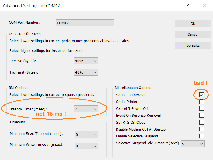
Screenshot with 'Advanced Settings' for a serial port adapter,
opened in Windows 10 via 'Control Panel' .. 'Device Manager' ..
'Ports (COM & LPT)' .. 'Port Settings' .. 'Advanced...' .
(*) With a different (non-FTDI) adapter, this problem did not exist.
Troubleshooting audio-via-UDP
When using UDP to distribute non-compressed audio streams in a local network, or even 'more local' within a single machine (using e.g. "localhost" or IPv4 address 127.0.0.1), there should be no trouble with the troughput. Spectrum Lab will try to send a new UDP frame ("datagram") to all receivers (listed in the 'Output Device / Stream / Driver' field) every two milliseconds. If Windows doesn't service the UDP-sending thread sufficiently often, the next time the thread has the chance to actually send a block of samples to all receivers, it will try to "catch up" by making the datagram longer than usual (up to 1470 bytes per payload in a UDP datagram, to avoid fragmentation or 'jumbo frames' that many embedded Ethernet- or WLAN/WiFi-modules don't support).Even though UDP is a 'fire-and-forget' protocol, the network driver in Windows sometimes could not keep up the pace. This happened especially when the destination (IPv4 address) didn't exist, or -when tried with "localhost"- the destination port was not open.
If that happens, Spectrum Lab will occasionally report a problem like the following (also coloured with a red background) in the Error History:
20:41:35 Calling waveInStart()

20:41:56 CSound: Output buffer overflow, UDP:6999, free=14788, needed=16384 samples
20:41:56 SoundThd: Tried to write 16384 samples, but only 14788 were written.
20:41:56 output buffers overflowed in SoundOutWrite
20:41:57 SoundErrorOut changed: output buffers overflowed
The yellow-coloured messages are subsequent errors from the
function that should have written a chunk of samples (here: 16684)
to SL's internal output buffer. But the root cause was that the UDP sending
function (sendto() in the Socket API) consumed too much time in the
UDP-sender thread, causing a backlash of samples to build up,
which after some time caused SL's "Output buffer overflow".The root cause for the above, or similar problems with UDP, were (roughly ordered by probability):
- Trying to send to a non-exising UDP port
- Trying to send over a UDP port that was already occupied by another application
- Trying to send over a weak Wireless LAN 'connection', when the network driver tried hard to get all packets 'across' (even though UDP doesn't guarantee that the packets will reach their receiver at all)
UDP port already in use ?
To check which UDP ports are already in used on your local machine ("localhost"), enter the following command in a 'cmd' window (on whereever you prefer to run command lines from):netstat -a -n -p udpThat command will usually show a few UDP ports already occupied, so don't pick any of those. Port 6999 was used throughout this manual as an example, because it's neither one of the "Well-known" UDP ports (with a fixed purpose) nor was it an 'officially registered' port at the time of this writing.
IP address (or 'remote host') reachable ?
If audio doesn't arrive at the UDP receiver, and the link involves a 'real' LAN- or WLAN interface (not just the "localhost" alias "127.0.0.1" in IPv4), try to 'ping' the destination's IP address, or hostname from the sending end. Use the simple old "ping" command (under Windows, from a command window, e.g. "cmd.exe"):ping my_udp_receiverwhere 'my_udp_receiver' is the hostname of the receiving PC. If you prefer use numeric IP addresses, "ping" also accepts that:
ping 192.168.178.20Example output:
pinging ....
Reply from 192.168.178.20: bytes=32 time=657ms TTL=128
Reply from 192.168.178.20: bytes=32 time=1234ms TTL=128
Reply from 192.168.178.20: bytes=32 time=136ms TTL=128
Reply from 192.168.178.20: bytes=32 time=83ms TTL=128
Troubleshooting Audio-via-TCP
< not finished yet ... >Last modified : 2023-10-23