Using a PC with soundcard as a VLF receiver
By Wolfgang Buescher, DL4YHF.
This article describes how to use your PC as a receiver for
narrow-band signals in the VLF radio spectrum. If you are more interested
in the reception of VLF natural radio (which is a broadband audio
application), there is another document for you.
Last modified: October 24, 2010.
Note: some links only work if this file is located in the help directory
of Spectrum Lab.
If so, you can return here to the main
index.
Check for the latest release of Spectrum Lab somewhere at
www.qsl.net/dl4yhf .
The PC is used to convert the VLF signal into an audible signal
-
Soundcard runs at a sample rate of 44100 or 48000 Hz (see
Notes)
-
Frequency is converted down to an audio frequency of 650Hz (or similar)
-
650 Hz "Audio IF" is passed through a narrow-band filter (100Hz BW)
-
The amplified audio is sent to the soundcard's D/A converter.
A PC with at least 266 MHz Pentium II, a soundcard (original Creative Labs
Soudblaster 16 has been tested, others work too, but some soundcards don't..)
For a start, just connect some meters of wire as an antenna to the MIC input
of the soundcard and try to listen to a local signal source (like a
tube TV set with flyback transformer). If you can get the system (described
below) to work, add a simple LC network parallel to the input as VLF
preselector. This will also protect your soundcard if you connect a longer
piece of wire. In my own tests I have found that the system is very sensitive
even with only passive components (including 2 protection diodes on a 200
meter long wire).
If there are no strong LF-, MF-, and HF-transmitters close to the receiver's
site, an active antenna like the one shown below may also work for VLF narrow
band reception (even though it was designed as a broadband antenna; see
VLF Natural Radio):
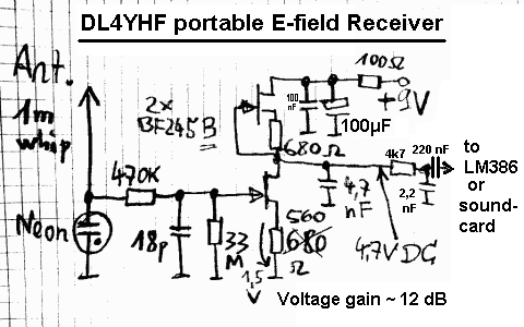
Note: The lower FET's source resistor should be tweaked
to have approximately half the supply voltage at its drain .
The neon lamp shall protect the FET against moderate statics,
but it's no protection against lightning. 4,7 nF should have been 4.7 nF (etc) -
old habits die hard .. it's the usual decimal separator in Germany.
All settings required for a receiver for 17.2kHz are contained in the user
profile "SaqRcvr1.usr" which is contained in Spectrum Lab's installation
archive (since V1.65).
(Why "SaqRcvr" ? SAQ is the name of
Grimeton Radio, a historic radio
station in Sweden. More infos are/were available at
www.alexander.n.se in Swedish language,
very impressive !).
After starting Spectrum Lab, go to the menu "Quick settings"..."User defined
Menus"..."Import". Select the file "SaqRcvr1.usr", "GBRrcvr.usr" or
" VlfStns.usr", then click "Ok, Load". This will install a new item in the
Quick Settings menu which you can use later to recall these settings.
-
Note for "old-time users" of Spectrum Lab:
-
The "SAQrcvr1.usr" file was modified in 2006. It uses the FFT-based
filter which didn't exist in earlier versions, making it much easier to operate.
The frequency conversion and filtering is now done entirely in the frequency
domain (inside the "Filter" runing in FFT mode), so the oscillator / mixer
/ IIR-filter is not required any longer. You will notice in the component
window that the oscillator- and mixer blocks are disabled. This is not an
error ! The oscillator + mixer blocks still exist for compatibility reasons,
but the preferred way to "shift frequencies" is the FFT-based filter
now.
Now switch to SpecLab's "Circuit" window (Menu "View/Windows...Spectrum Lab
Components"). If everything is ok with the soundcard, you see something like
this :
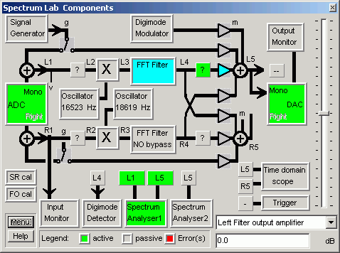
(component window after loading the application "SAQ - Receiver #1" )
If one of the function blocks is colored red, the program has detected a
malfunction- maybe the PC is too slow (it did work with a 266MHz-P2) or the
soundcard is not supported, or the soundcard doesn't support the sampling
rate (which is either 44100 or 48000 samples/second. Good cards & drivers
support BOTH). If necessary, change the sampling rate in SL's
audio settings .
Now connect a headphone to the soundcard's output. You should hear a weak
650-Hz signal. Otherwise you must find the correct audio settings using the
control program for your soundcard (some info is in SpecLab's
help system, but SpecLab cannot adjust the audio
gain in the soundcard itself).
VFO Control
Note: This was more complicated in older versions. Now frequency
conversion and filtering is done inside the FFT-filter; so the oscillator
+ mixer/multiplier are not used in this setup any longer)
To modify the VLF "RX-frequency", move the red "VFO" marker on the frequency
scale of the spectrum plot or waterfall display in the main window. Move
the mouse across the frequency scale, and hold the left mouse button pressed
to move the marker.
Note: The 'connection' of the red
frequency marker ("diamond") for
the VFO frequency is a programmed feature of the "VLF-Receiver" profile.
How this works internally is explained
here in the SpecLab manual, but you
don't need to know it if you only want to use this feature.
Receiver Gain Control
The "SAQ receiver" application uses one of Spectrum Lab's DSP blackboxes
as automatic gain control. This is the green square with the questionmark
in the circuit diagram. If necessary, the AGC can be configured as explained
here. But for most applications
the default setting should be ok.
If the audio output is too weak, though the soundcard volume control is at
maximum, you can add more gain by software. If you click at the amplifier
symbol in the circuit diagram (triangle just right to DSP blackbox), a small
dialog opens where you can enter the gain, or connect the gain control to
the vertical slider on the left side of the component window shown above.
If you don't hear anything: To verify if a signal is getting in, activate
the "Input Monitor" (click..). Increase the "Vmag" value of the oscilloscope
until you can see a signal.
If you cannot hear any audio coming out of the soundcard, activate the "Signal
Generator" and connect it to the sound output (click on the function
block and then start the sine generator). If you still can't hear anything,
check the Volume Control from the program "sndvol32.exe" which is part of
Windows. To modify the "recording" settings (here: Sound IN), you must change
the properties in the "Options" menu of sndvol32. (Sorry, Spectrum Lab cannot
find the optimum settings itself. It can not access the soundcard's "Mixer"
like other nice programs ;-).
Modifying the Filter
characteristics
Depending on the bandwidth of the signal you are looking for, you may want
to use different audio filter characteristics. A 50 Hz filter is often a
good choice for medium-speed morse transmissions, while 500 Hz may be better
for digital transmissions like RTTY and PSK. There is a number of
"pre-configured" filters which you can load from disk files, but you can
also create your own filters:
-
-
The very old way (before Spectrum Lab V1.7)
-
Click on the "Filter" block and switch to the tab "IIR-Design 2". Load one
of the "650-Hz-filter" designs which are part of the installation archive.
The default "SAQ"-filter is a 4-stage IIR filter, each stage is a second
order IIR-filter used as a bandpass. The gain, center frequency and bandwidth
of each stage can be set individually. Modify a parameter in the filter designer
table, then click "Calculate" to make the change effective. You may customize
the filter for your own requirements, change the bandwidth, center frequencies
or the number of stages used. But it's not easy to spread the poles to get
exactly the frequency response you want, so you should use the "IIR-Designer
3" mentioned below, or jump right to the FFT-based
filter which is the preferred method since SpecLab V2.6 .
-
The second method (a bit easier, since Spectrum Lab V1.7, tnx M0BMU):
-
Click on the "Filter" block and switch to the tab "IIR-Design 3". Enter a
filter center frequency and bandwidth of your own, then click "Apply". More
information about the types of narrow-band audio filters can be found
here. You can also control the audio
filter's center frequency from a small slider on the frequency axis
of the waterfall, quite like the VFO control.
-
The third method (much easier, since Spectrum Lab V2.6):
Use the FFT-based filter !
-
Much easier to use than the "classic" FIR- and IIR-based filters is the FFT-based
filter. There is an extra control tab for it in the filter control window.
Select "bandpass" characteristics, the desired center frequency, and the
filter bandwidth. An FFT size of 2048 or 4096 (within the filter !) is ok
for this application. You can do even more with this filter: Let it do the
downconversion too ! The function of the FFT-based filter is explained
here .
If you don't want to learn how all this works internally, but simply use
it instead, load the preconfigured application "SAQrcvr1.usr" from the "Quick
Settings" menu. It was modified in 2006 so it uses the FFT-based filter for
"downconversion" and for narrow-band filtering at the same time. Move the
red "diamond" on the main frequency scale with the mouse to tune this receiver
to any frequency you like (not just 17.2 kHz for which the receiver was
originally designed).
-
-
back to top
The file "VlfStns.usr" has the frequency markers set to some VLF transmitters
which can/could be heard in Europe. This makes identifying them on the waterfall
display easier. In addition, there is a
'radio station list' which
also contains the frequencies of some 'known' VLF transmitters.
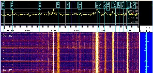
(spectrogram with radio station display)
Some of these stations are:
| Frequency (Hz) |
Callsign |
Station |
Country |
Mode, Remarks |
11905,
12500,
12649,
12695,
13281,
14881,
15625 (!) |
? |
RSDN-20
("Alpha")
navigation system.
See notes below table. |
RUS |
Pulses
("beep,beep")
all seven frequencies heard in Dec. 2003 |
| 15100 |
? |
? |
? |
|
| 15625 |
-- |
Your neighbour's (tube-) TV |
|
Continuous line sync signal,
emitted by flyback transformer |
| 15980 |
GBR |
Navy Rugby |
G |
RTTY (MSK)
100 Bd
heard in March 2003
went QRT in 2003 (*) |
| 16300 |
VTX1 |
Navy Vijayanarayanam |
IND |
CW, rare |
| 16400 |
JXN |
Navy Novik |
NOR |
RTTY (MSK)
200 Bd
heard in March 2003 |
| 16800 |
? |
|
|
RTTY |
| 17000 |
VTX2 |
Navy Vijayanarayanam |
IND |
CW, rare |
| 17200 |
SAQ |
Grimeton |
S |
CW, historical transmitter
(Alexanderson alternator)
1-2 times per year |
| 18100 |
RDL,.. |
Navy Krasnodar + .. |
RUS |
RTTY (multi-tone FSK?)
heard in March 2003 |
| 18200 |
VTX3 |
Navy Vijayanarayanam |
IND |
CW, RTTY, rare |
| 18300 |
HWU |
Navy Le Blanc |
F |
RTTY (MSK)
200 Bd
heard in March 2003 |
| 19000 |
GBZ(?) |
Navy Criggion (?) |
G |
RTTY (MSK)
not heard in 2003 yet |
| 19200 |
? |
? |
? |
RTTY (MSK)
heard in March 2003 |
| 19600 |
GBZ(?) |
Navy Criggion (?) |
G |
RTTY (MSK) 200 Bd
heard in March 2003 |
| 20270 (+/-) |
ICV(?) |
Navy Tavolara, Sardinia |
I |
RTTY (MSK)
heard in March 2003 |
| 20900 |
HWU |
Navy Le Blanc |
F |
RTTY (MSK)
heard in March 2003 |
| 21100 |
RDL |
Navy, Krasnodar et al |
RUS |
RTTY (MSK)
heard in March 2003 |
| 22100 |
? |
Navy Anthorn |
G |
RTTY (MSK)
heard in March 2003 |
| 23400 |
DHO38 |
Navy Ramsloh |
D |
RTTY (MSK)
heard in March 2003 |
|
|
|
|
|
|
|
|
|
|
A complete list of VLF stations can be found Renato's VLF Open Lab site,
see links at the end of this document. Or scan the net for Klaus Betke's
LF pages.
Notes on certain VLF stations:
-
ALPHA beacons
-
Read this chapter with the description
of an experiment which can be done with SpecLab, a small loop antenna, and
this old Russian navigation system which still existed in 2006.
-
GBR
-
The British station GBR went QRT in 2003, but you may find an old transmission
from this station in morse code in your music archive ! When Mike Oldfield
recorded "Tubular Bells" in 1972 and 1973 at The Manor studio, some of the
recording equipment wasn't properly shielded, so the CW transmission from
GBR was recorded on the master tape - possibly without the audio engineer's
knowledge. You can see these these morse code transmissions in the spectrogram
or make them audible again (play directly from CD or from a WAVE file, but
do not try this with lossy MP3 files - the MP3 compression removes everything
above 16 kHz ). There is a predefined configuration for SpecLab named
"GBR_CD.USR" which can make the morse code on Tubular Bells audible and visible
(16 kHz converted down to 650 Hz, and narrow-band filtered; morse characters
are visible on the spectrogram screen).
ALPHA is a Russion navigation system in the VLF band which you can receive
with a simple loop antenna (at least in Europe). Some ALPHA frequencies are
listed here . With a system of two orthogonal
loop antennas and a stereo soundcard, the transmission cycle can be analysed
with a preconfigured setup from SL's installation archive :
Load the application "AlphaTrg.usr" and see what happens on the
screen (most likely, you will need to adjust the 'contrast' and 'brightness'
controls for the waterfall because the input level from your VLF antenna
will be different). What the "Triggered ALPHA-Beacon Monitor" does is:
-
Wait for the begin of a new ALHA transmission cycle.
For this purpose, the spectrogram runs in
'triggered SWEEP mode'.
The trigger is connected to a pulse generator which fires once every 3.594
seconds (- or is it 3.6 seconds as mentioned somewhere on the internet ?
).
-
Draw one spectrogram screen and then stop, adding the new spectra to the
previously recorded ones : Every line of the waterfall screen has its own
average-buffer.
-
Back to step 1 to wait for the next cycle
If everything works ok, the noise-reducing effect of the averaging may look
like this (left screenshot without, right screenshot with 10-fold averaging
) :
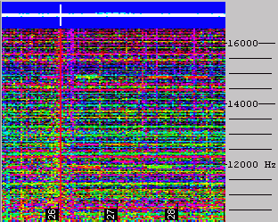
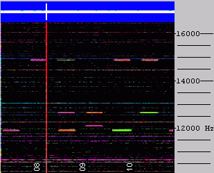
The pretrigger was set to 1 second for this test, so the trigger pulse is
visible on the blue amplitude bar. The VLF
RDF antenna was deliberately placed
in a noisy environment (indoors), so the ALPHA pulses were barely audible
in the noise. The waterfall 'contrast' was set to a high value; the same
settings were used for both screenshots.
How does it work ?
Because the ALPHA-beeps will always appear on the same screen positions,
the average-buffers will slowly fill up with each new scan. The noise (if
randomly distributed) will seem to get weaker with each new scan. For example,
if there was a random 1-millivolt "beep" in one sweep, it will appear
like a 0.1 mV signal after ten sweeps are averaged. After 1000 averages,
1 mV will be divided down to 1 uV. Ok, what else can you do with this ?
Of course, this principle can be used for all kinds of weak but periodic
tone signals - for example, for EME-testing purposes (Earth-Moon-Earth).
If several hundred VHF-"pings" were sent to the moon and the echo received
with a small yagi antenna, it is possible to see the echo on the 'averaged
synchronized spectrogram' even if a lot of dB's were missing to copy the
signal by ear ( successfully tested at the local amateur radio station, see
configuration EME_Ping_Test.usr ).
A similar configuration (which works without an off-air signal) is contained
in the SL installer: Load the configuration 'TrigSpectTest1.usr'.
When reprogrammed for the ALPHA beacon cycle, that configuration would also work
with a single (non-RDF) VLF antenna.
back to top
-
Phantom signals when using 48kHz sample rate
-
(December 1, 2001)
Be careful when using 48000 samples per second. Most modern audio cards really
support this sample rate which is nice to receive signals up to 24 kHz. Some
cards don't and you'll get an error message when you try to use this sample
rate. In this case, buy another audio card or stick to 44100 samples per
second which is a widely used standard sampling rate. Other cards like the
onboard "ESS AudioDrive" in the author's notebook play dirty tricks when
you use 48000 samples per second, here is just one example:
Phantom signals appeared on the waterfall, a signal on 20.7 kHz also appeared
(a bit weaker) on 16.8 and 12.9 kHz !
(go figure: 48kHz-44.1kHz = 3.9kHz ; 20.7kHz - 3.9kHz = 16.8kHz ; 20.7 kHz
- 2*3.9 kHz = 12.9 kHz) It seems that some cards don't really sample the
analog input at 48000 samples per second, instead they sample at 44100 samples
per second and 'duplicate' a part of the samples.. what a lousy trick !
-
Even higher sampling rates and bandwidths
-
There are now some expensive soundcards on the market which support true
96kHz sampling rate, or even more. If you have one of these cards, try to
set the sampling rate to 96000 samples/second. With some luck, you may be
able to receive VLF stations up to 40..44 kHz (to receive 48kHz is not possible
because of the soundcard's anti-aliasing filter). Note: I once bought Creative
Lab's "Extigy" card because it said "supports 96 kHz sampling" on the box,
only to find out that the A/D converter in fact only runs at 48 kHz. I later
tried the Audigy 2 ZS, and got it working after some struggle with
unwanted audio bypass from the "Line-In"
to "Line-Out" .
Some higher-priced cards can sample at 192 kHz, look
here for details.
Another possibility to effectively double the bandwith is feeding a quadrature
signal (I/Q signal) into the input
of your soundcard (Note: This requires a "stereo line input", not
just a "microphone input" - consider this before buying a new notebook
;-)
back to top of page
User feedback is welcome. It is the most effective way to make the program
better. The email address can be found on the author's homepage if
you look a bit closer ;-)
If you have optimized the settings to reveive other VLF stations let me know.
I will post it somewhere on my website so others can also use them. Because
Spectrum Lab is still under construction, some of the functions described
above may be slightly different now, but the basic principle remains the
same.
If you are interested in VLF reception, check these sites...
Good luck !
Wolfgang ("Wolf", DL4YHF).


