
|
Electrostatic Motors Are Powered By Electric Field of the EarthBy C.L. Stong, October 1974 |
Last update |
ALTHOUGH no one can make a perpetual motion machine, anyone can tap the earth's electric field to run a homemade motor perpetually. The field exists in the atmosphere between the earth's surface and the ionosphere as an electric potential of about 360 000 volts. Estimates of the stored energy range from a million kilowatts to a billion kilowatts.
Energy in this form cannot be drawn on directly for driving ordinary electric motors. Such motors develop mechanical force through the interaction of magnetic fields that are generated with high electric current at low voltage, as Michael Faraday demonstrated in 1821. The earth's field provides relatively low direct current at high voltage, which is ideal for operating electrostatic motors similar in principle to the machine invented by Benjamin Franklin in 1748.
Motors of this type are based on the force of mutual attraction between unlike electric charges and the mutual repulsion of like charges. The energy of the field can be tapped with a simple antenna in the form of a vertical wire that carries one sharp point or more at its upper end. During fair weather the antenna will pick up potential at the rate of about 100 volts for each meter of height between the points and the earth's surface up to a few hundred feet. At higher altitudes the rate decreases. During local thunderstorms the pickup can amount to thousands of volts per foot. A meteorological hypothesis is that the field is maintained largely by thunderstorms, which pump electrons out of the air and inject them into the earth through bolts of lightning that continuously strike the surface at an average rate of 200 strokes per second.
Why not tap the field to supplement conventional energy resources ? Several limitations must first be overcome. For example, a single sharp point can draw electric current from the surrounding air at a rate of only about a millionth of an ampere. An antenna consisting of a single point at the top of a 60-foot wire could be expected to deliver about a microampere at 2 000 volts; the rate is equivalent to .002 watt. A point-studded balloon tethered by a wire at an altitude of 75 meters might be expected to deliver .075 watt. A serious limitation appears as the altitude of the antenna exceeds about 200 meters. The correspondingly higher voltages become difficult to confine.
At an altitude of 200 meters the antenna should pick up some 20 000 volts. Air conducts reasonably well at that potential. Although nature provides effective magnetic materials in substances such as iron, nickel and cobalt, which explains why the electric-power industry developed around Faraday's magnetic dynamo, no comparably effective insulating substances exist for isolating the high voltages that would be required for electrostatic machines of comparable power. Even so, electrostatic motors, which are far simpler to build than electromagnetic ones, may find applications in special environments such as those from which magnetism must be excluded or in providing low power to apparatus at remote, unmanned stations by tapping the earth's field.
Apart from possible applications electrostatic motors make fascinating playthings. They have been studied extensively in recent years by Oleg D. Jefimenko and his graduate students at West Virginia University. The group has reconstructed models of Franklin's motors and developed advanced electrostatic machines of other types.
Although Franklin left no drawing of his motor, his description of it in a letter to Peter Collinson, a Fellow of the Royal Society, enabled Jefimenko to reconstruct a working model [ see Fig 1 ]. Essentially the machine consists of a rimless wheel that turns in the horizontal plane on low-friction bearings. Each spoke of the "electric wheel", as Franklin called the machine, consists of a glass rod with a brass thimble at its tip. An electrostatic charge for driving the motor was stored in Leyden jars. A Leyden jar is a primitive form of the modern high-voltage capacitor. Franklin charged his jars with an electrostatic generator.
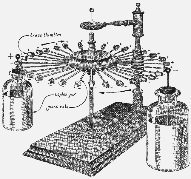
Fig 1 - Benjamin Franklin's electrostatic motor
The high-voltage terminals of two or more Leyden jars that carried charges of opposite polarity were positioned to graze the thimbles on opposite sides of the rotating wheel. The motor was started by hand. Thereafter a spark would jump from the high-voltage terminal to each passing thimble and impart to it a charge of the same polarity as that of the terminal. The force of repulsion between the like charges imparted momentum to the wheel.
Conversely, the thimbles were attracted by the oppositely charged electrode of the Leyden jar Franklin placed on the opposite side of the wheel. As the thimbles grazed that jar, a spark would again transfer charge, which was of opposite polarity. Thus the thimbles were simultaneously pushed and pulled by the high-voltage terminals exactly as was needed to accelerate the wheel.
Franklin was not altogether happy with his motor. The reason was that running it required, in his words, "a foreign force, to wit, that of the bottles". He made a second version of the machine without Leyden jars.
In this design the rotor consisted principally of a 17-inch disk of glass mounted to rotate in the horizontal plane on low-friction bearings. Both surfaces of the disk were coated with a film of gold, except for a boundary around the edge. The rotor was thus constructed much like a modern flat-plate capacitor.
Twelve evenly spaced metal spheres, cemented to the edge of the disk, were connected alternately to the top and bottom gold films. Twelve stationary thimbles supported by insulating columns were spaced around the disk to graze the rotating metal spheres. When Franklin placed opposite charges on the top and bottom films and gave the rotor a push, the machine ran just as well as his first design, and for the same reason. According to Franklin, this machine would make up to 50 turns a minute and would run for 30 minutes on a single charge.
Jefimenko gives both motors an initial charge from a 20 000 volt generator. They consume current at the rate of about a millionth of an ampere when they are running at full speed. The rate is equivalent to .02 watt, which is the power required to lift a 20 gram weight 10 centimeters (or an ounce 2.9 inches) in one second.
Jefimenko wondered if Franklin's motor could be made more powerful. As Jefimenko explains, the force can be increased by adding both moving and fixed electrodes. This stratagem is limited by the available space. If the electrodes are spaced too close, sparks tend to jump from electrode to electrode around the rotor, thereby in effect short-circuiting the machine. Alternatively the rotor could be made cylindrical to carry electrodes in the form of long strips or plates. This scheme could perhaps increase the output power by a factor of 1 000.
Reviewing the history of electrostatic machines, Jefimenko came across a paper 3 published in 1870 by Johann Christoff Poggendorff, a German physicist. It described an electrostatic motor fitted with a rotor that carried no electrodes. The machine consisted of an uncoated disk of glass that rotated in the vertical plane on low-friction bearings between opposing crosses of ebonite. Each insulating arm of the crosses supported a comblike row of sharp needle points that grazed the glass.
When opposing combs on opposite sides of the glass were charged in opposite polarity to potentials in excess of 2 000 volts, air in the vicinity of the points on both sides of the glass was ionized. A bluish glow surrounded the points, which emitted a faint hissing sound. The effect, which is variously known as St. Elmo's fire and corona discharge, deposited static charges on both sides of the rotor.
Almost the entire surface of the glass acquired a coating of either positive or negative fixed charges, depending on the polarity of the combs. The forces of repulsion and attraction between glass so charged and the combs were substantially larger than they were in Franklin's charged thimbles. The forces were also steadier, because in effect the distances between the combs and the charged areas remained constant. It should be noted that adjacent combs on the same side of the glass carried charges of opposite polarity, so that the resulting forces of attraction and repulsion acted in unison to impart momentum to the disk, as they did in Franklin's motor.
By continued experimentation Poggendorff learned that he should slant the teeth of the combs to spray charge on the glass at an angle. The resulting asymmetrical force made the motor self-starting and unidirectional. When the teeth were perpendicular to the glass surface, the forces were symmetrical, as they were in Franklin's motor. When the machine was started by hand, it ran equally well in either direction.
Poggendorff was immensely pleased by the rate at which his machine converted charge into mechanical motion. He concluded his paper with a faintly odious reference to Franklin's device. "That such a quantity of electricity must produce a far greater force than that in the [Franklin] electric roasting spit," he wrote, "is perfectly obvious and nowadays would not be denied by Franklin himself. With one grain of gunpowder one cannot achieve so much as with one hundred pounds".
Electrostatic motors are now classified in general by the method by which charge is either stored in the machine or transferred to the rotor. Poggendorff's machine belongs to the corona type, which has attracted the most attention in recent years. Although its measured efficiency is better than 50 percent, Poggendorff regarded it merely as an apparatus for investigating electrical phenomena. He wrote that "it would be a sanguine hope if one wanted to believe that any useful mechanical effect could be achieved with it".
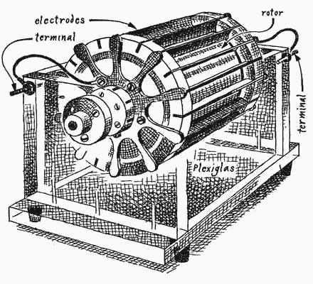
Fig 2 - Oleg D. Jefimenko's corona motor
Poggendorff's negative attitude toward the usefulness of his design may well have retarded its subsequent development. A modern version of the machine constructed in Jefimenko's laboratory has an output of approximately .1 horsepower. It operates at speeds of up to 12 000 revolutions per minute at an efficiency of substantially more than 50 percent. In one form the modern corona motor consists of a plastic cylinder that turns on an axial shaft inside a concentric set of knife-edge electrodes that spray charge on the surface of the cylinder [ see Fig 2 ]. Forces that act between the sprayed charges and the knife-edge electrodes impart momentum to the cylinder.
Machines of this kind can be made of almost any inexpensive dielectric materials, including plastics, wood and even cardboard. The only essential metal parts are the electrodes and their interconnecting leads. Even they can be contrived of metallic foil backed by any stiff dielectric. The shaft can be made of plastic that turns in air bearings. By resorting to such stratagems experimenters can devise motors that are extremely light in proportion to their power output. Corona motors require no brushes or commutators. A potential of at least 2 000 volts, however, is essential for initiating corona discharge at the knife-edges.
A smaller and simpler version of the machine was demonstrated in 1961 by J. D. N. Van Wyck and G. J. Kühn in South Africa. This motor consisted of a plastic disk about three millimeters thick and 40 millimeters in diameter supported in the horizontal plane by a slender shaft that turned in jeweled bearings. Six radially directed needle points grazed the rim of the disk at equal intervals. When the machine operated from a source of from 8 000 to 13 000 volts, rotational speeds of up to 12 000 revolutions per minute were measured.
I made a corona motor with Plexiglas tubing two inches in diameter and one and a half inches long. It employed stiffbacked single-edge razor blades as electrodes. The bore of the tube was lined with a strip of aluminum foil, a stratagem devised in Jefimenko's laboratory to increase the voltage gradient in the vicinity of the electrodes and thus to increase the amount of charge that can be deposited on the surface of the cylinder. I coated all surfaces of the razor blades except the cutting edges and all interconnecting wiring with "anticorona dope", a cementlike liquid that dries to form a dielectric substance that reduces the loss of energy through corona discharges in nonproductive portions of the circuit.
The axial shaft that supports the cylinder on pivot bearings was cut out of a steel knitting needle. The ends of the shaft were ground and polished to 30 degree points. To form the points I chucked the shaft in an electric hand drill, ground the metal against an oilstone and polished the resulting pivots against a wood lap coated with tripoli.
The bearings that supported the pivots were salvaged from the escapement mechanism of a discarded alarm clock. A pair of indented setscrews could be substituted for the clock bearings. The supporting frame was made of quarter-inch Lucite. The motor can be made self-starting and unidirectional by slanting the knife-edges. Those who build the machine may discover, as I did, that the most difficult part of the project, balancing the rotor, is encountered after assembly. The rotor must be balanced both statically and dynamically.
Static balance was achieved by experimentally adding small bits of adhesive tape to the inner surface of the aluminum foil that lines the cylinder until the rotor remained stationary at all positions to which it was set by hand. When the rotor was balanced and power was applied, the motor immediately came up to speed, but it shook violently. I had corrected the imbalance caused by a lump of cement at one end of the rotor by adding a counterweight on the opposite side at the opposite end of the cylinder. Centrifugal forces at the ends were 180 degrees out of phase, thus constituting a couple.
The dynamic balancing, which is achieved largely by cut-and-try methods, took about as much time as the remainder of the construction. To check for dynamic balance suspend the motor freely with a string, run it at low speed and judge by the wiggle where a counterweight must be added. Adhesive tape makes a convenient counterweight material because it can be both applied and shifted easily.
I made the motor as light and frictionless as possible with the objective of operating it with energy from the earth's field. The field was tapped with an antenna consisting of 300 feet of No. 28 gauge stranded wire insulated with plastic. It is the kind of wire normally employed for interconnecting electronic components and is available from dealers in radio supplies.
The upper end of the wire was connected to a 20-foot length of metallic tinsel of the kind that serves for decorating a Christmas tree. The tinsel functioned as multiple needle points. Strips cut from window screening would doubtless work equally well.
The upper end of the tinsel was hoisted aloft by a cluster of three weather balloons. Such balloons, each three feet in diameter, and the helium to inflate them are available from the Edmund Scientific Co. (300 Edscorp Building, Barrington, N.J. 08007). The weight in pounds that a helium-filled balloon of spherical shape can lift is roughly equal to a quarter of the cube of its radius in feet. To my delight the motor began to run slowly when the tinsel reached an altitude of about 100 feet. At 300 feet the rotor made between 500 and 700 revolutions per minute.
A note of warning is appropriate at this point. Although a 300-foot vertical antenna can be handled safely in fair weather, it can pick up a lethal charge during thunderstorms. Franklin was incredibly lucky to have survived his celebrated kite experiment. A European investigator who tried to duplicate Franklin's observations was killed by a bolt of lightning. The 300-foot antenna wire can hold enough charge to give a substantial jolt, even during fair weather. Always ground the lower end of the wire when it is not supplying a load, such as the motor.
To run the motor connect the antenna to one set of electrodes and ground the other set. Do not connect the antenna to an insulated object of substantial size, such as an automobile. A hazardous charge can accumulate. Never fly the balloon in a city or in any other location where the antenna can drift into contact with a high-voltage power line. Never fly it below clouds or leave it aloft unattended.
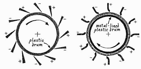
Fig 3 - Conventional electrodes (left) and improved electrodes (right)
A variety of corona motors have been constructed in Jefimenko's laboratory. He has learned that their performance can be vastly improved by properly shaping the corona-producing electrodes [ see Fig 3 ]. The working surface of the rotors should be made of a fairly thin plastic, such as Plexiglas or Mylar. Moreover, as I have mentioned, the inner surface of the cylinder should be backed by conducting foil to enhance the corona. Effective cylinders can be formed inexpensively out of plastic sewer pipe. Corona rotors can of course also be made in the form of disks.
One model consists of a series of disks mounted on a common shaft. Double-edged electrodes placed radially between adjacent disks function much like Poggendorff's combs. This design needs no foil lining or backing because a potential gradient exists between electrodes on opposite sides of the disks. It is even possible to build a linear corona motor, a design that serves to achieve translational motion. A strip of plastic is placed between sets of knife-edge electrodes slanted to initiate motion in the desired direction.
Notwithstanding the problem of handling potentials on the order of a million volts without effective insulation materials, Jefimenko foresees the possibility of at least limited application of corona power machines. In The Physics Teacher (March, 1971) he and David K. Walker wrote: "These motors could be very useful for direct operation from high-voltage d.c. transmission lines as, for example, the 800 kV Pacific Northwest-Southwest Intertie, which is now being constructed between the Columbia River basin and California. It is conceivable that such motors could replace the complex installations now needed for converting the high-voltage d.c. to low-voltage a.c. All that would be required if corona motors were used for this purpose would be to operate local low-voltage a.c. generators from corona motors powered directly from the high-voltage d.c. line".
As Jefimenko points out, a limiting factor of the corona motor is its required minimum potential of 2 000 volts. This limitation is circumvented by a novel electrostatic motor invented in 1961 by a Russian physicist, A. N. Gubkin. The motor is based on an electret made in 1922 by Mototaro Eguchi, professor of physics at the Higher Naval College in Tokyo.
An electret is a sheet or slab of waxy dielectric material that supports an electric field, much as a permanent magnet carries a magnetic field. Strongly charged carnauba-wax electrets are available commercially, along with other electrostatic devices, from the Electret Scientific Company (P.O. Box4132, Star City, W.Va. 26505). A recipe for an effective electret material is 45 percent carnauba wax, 45 percent water-white rosin and 10 percent white beeswax. Some experimenters substitute Halowax for the rosin.
The ingredients are melted and left to cool to the solid phase in a direct-current electric field of several thousand volts. The wax continues to support the field even though the external source of potential is turned off [ see "The Amateur Scientist" column, SCIENTIFIC AMERICAN, November 1960, and July 1968 ]. The electret reacts to neighboring charges exactly as though it were a charged electrode, that is, it is physically attracted or repelled depending on the polarity of the neighboring electrode.
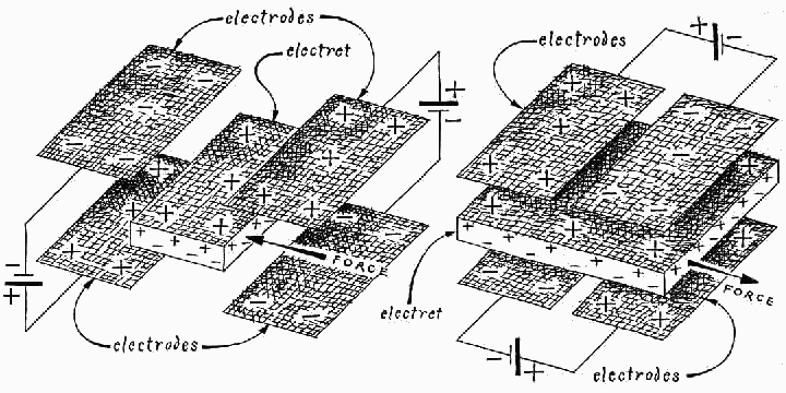
Fig 4 - Scheme of A.N. Gubkin's electret (left) and slot-effect motor (right)
Gubkin harnessed this effect to make a motor. The rotor consisted of a pair of electrets in the shape of sectors supported at opposite ends of a shaft. The center of the shaft was supported transversely by an axle. When the rotor turned, the electrets were swept between adjacent pairs of charged metallic plates, which were also in the form of sectors.
The plates were electrified by an external source of power through the polarity-reversing switch known as a commutator. The commutator applied to the electrodes a charge of polarity opposite to the charge of the attracted electret. As the electret moved between the attracting plates, however, the commutator switched the plates to matching polarity. The alternate push and pull imparted momentum to the rotor in exact analogy to Franklin's motor.
Gubkin's motor was deficient in two major respects. The distances between the electrodes and the electrets were needlessly large, so that the forces of attraction and repulsion were needlessly weak. Moreover, during the electret's transit between electrodes its surfaces were unshielded. Unshielded electrets attract neutralizing ions from the air and lose their charge within hours or days.
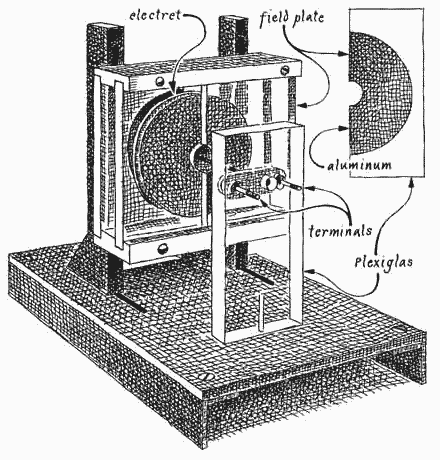
Fig 5 - Jefimenko's slot-effect electret motor
Both inherent deficiencies of Gubkin's motor have been corrected in Jefimenko's laboratory by taking advantage of what is termed the slot effect. Instead of sandwiching the electret alternately between pairs of metal plates, Jefimenko employs opposing pairs of adjacent plates [ see Fig 5 ]. The adjacent plates are separated by a narrow slot. When adjacent plates carry charges of opposite polarity, the electret experiences a force at right angles to the slot and in the plane of the electret. The strength of the force is at a maximum because the electret is close to the electrodes. Simultaneously the electrodes function as shields to prevent the neutralization of the electret by free ions.
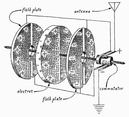
Fig 6 - Circuit arrangement for the slot-effect electret motor
The electret is mounted on a four-millimeter shaft of plastic that turns in jeweled bearings. The conducting surfaces of the commutator consist of dried India ink. The brushes are one-millimeter strips of kitchen aluminum foil. The motor operates on a few microwatts of power.
Jefimenko has demonstrated a similar motor that was designed to turn at a rate of about 60 revolutions per minute and develop a millionth of a horsepower on a 24-foot antenna having a small polonium probe at its upper end. (By emitting positive charges probes of this type tap the earth's field somewhat more efficiently than needle points do.) The performance of the motor easily met the design specifications. The charm of these motors lies in the fact that, although they do not accomplish very much, they can run forever.
ATMOSPHERIC ELECTRICITY. J. Alan Chalmers. Pergamon Press, 1968.
ELECTROSTATIC MOTORS: THEIR HISTORY, TYPES AND PRINCIPLES OF OPERATION. Oleg D. Jefimenko. Electret Scientific Company, 1973.
ELECTROSTATICS AND ITS APPLICATIONS. Edited by A. D. Moore. John Wiley & Sons, 1973.
Suppliers and Organizations
The Society for Amateur Scientists (SAS) is a nonprofit research and educational organization dedicated to helping people enrich their lives by following their passion to take part in scientific adventures of all kinds.
The Society for Amateur Scientists
5600 Post Road, #114-341
East Greenwich, RI 02818
Phone: 1-401-823-7800
Internet: http://www.sas.org/
Acknowledgements to Michael Foster
who provided me with the article above and the true name - Poggendorff's motor - for my rotating disk motor.
Robert L.E.Billon, June 2002
Page URL http://f3wm.free.fr/sciences/jefimenko.html