| Nikola Tesla | Theory | Basics | Measurements | My first TC | The Tesla Magnifier | Links | Homepage |
|
My magnifier project |
Last update |
Inspired by the first rate text from Steve Dodder (see The Tesla Magnifier page), I decided to build a magnifier, a rather modest one. Begining by June 2001 I coiled the primary, secondary and extra coils, build a Multi Microwave Oven Cap (MMOC) and a protection circuit with an auxilliary adjustable spark gap. The pictures are here. In the mean time my RSG will be built, the auxilliary adjustable gap may well be my main gap. Initially the adjustable spark gap is a substitute in the case the RSG fails to fire.
By now (Aug 29, 2002), the following components are available, have been built or are projected :
|
PRIMARY Ø = 300 mm h = 180 mm 15 turns cylindrical spiraled Coper pipe Ø6.3 mm / 4.5 mm Section 15.27 mm² Pipe lenght 14.08 m Lp = 64 µH (calculated) = 60 µH (measured) Rp = 15.8 milli-ohms (calculated) |
SECONDARY PVC pipe Ø = 20 cm 183 turns, tight wound Wire Ø = 1 mm Wire lenght = 115.55 m Lenght of coiling = 20 cm Ls = 4.658 mH (calculated) = 4.62 mH (measured) Rs = 2.53 ohms (calculated) = 2.53 ohms (measured) |
EXTRA COIL PVC pipe Ø = 20 cm 448 turns, tight wound Wire Ø = 0.8 mm Wire lenght = 281.48 m Lenght of coiling = 40 cm Le = 16.50 mH (calculated) = 16.4 mH (measured) Re = 9.63 ohms (calculated) = 9.63 ohms (measured) |
ALTERNATE EXTRA COIL PVC pipe Ø = 20 cm 750 turns, tight wound Wire Ø = 0.6 mm Wire lenght = 472.65 m Lenght of coiling = 50 cm Le = 38.13 mH (calculated) = 38 mH (measured) Re = 28.5 ohms (measured) |
|
CAPS MMOC 15 x 0.6 µF±4% / 2500 V Resulting in 40 nF / 37500 V Measured : 39.1 nF |
TOROID TERMINAL Øext d1 = 455 mm Øsection d2 = 127 mm Corrugated aluminium pipe Finishing layer TBD (Work is in sleep mode !) |
ALTERNATE SPHERICAL TERMINAL Ø D = 400 mm made with 2 ½spherical metal pieces from an old luminary |
POWER SUPPLY NST 10 kV / 100 mA Measured : 139 mA VARIAC 0-270 V @ 8 A |
|
SPARK GAP (SRSG) Friendly provided by F. Gallet, from Tesla Coil France |
PROTECTION 2 toroidal core choke inductances, each 10 mH + an adjustable gap |
By the autumn 2001 I acquired a low coast grinding tool powered by a 200 watts asynchronous motor and get its armature (rotor) machined at a mechanics shop in order to give it two flats for synchronous operation. I made a little stroboscope in order to verify the synchronism of my motor. I used a white cardboard disk with a half painted in marine, fixed on the axle of the motor. The test results are perplexing me. There is some jitter and by now I am unable to said which has jitter, the motor itself or my stroboscopic flashing light ! Possibly a more sophisticated trigger of the flash, with zero crossing detection of the mains sinusoidal voltage, may solve the problem.
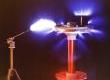
See a picture of a provisional assembly with the spherical terminal. The resonant frequency is 140 kHz.
Spring 2006 - Some years and a few health problems later... The modified asynchronous motor was abandonned. In the meantime a friend of mine, from Tesla Coil France, provided me with an SRSG. Tests were conducted using the SRSG and the MMOC. The results were disappointing, the parasitic inductance of the capacitors seams to be the culprit. A good, pulse oriented capacitor is hardly wanted !
Do not experiment with Tesla Coils if you do not understand well what you are doing. Any error may be fatal and the right to do it again is rarely granted. So your first mistake may be the last.
|
|
Nikola Tesla | Theory | Basics | Measurements | My first TC | The Tesla Magnifier | Links | Homepage |
scrolling menu noframes menu
Page URL http://f3wm.free.fr/tesla/mag_project.html
© Robert L.E. Billon, 2000, 2010