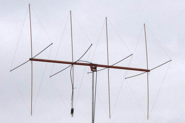
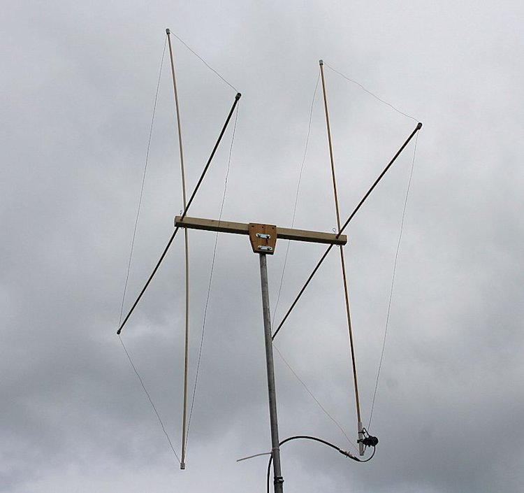
This antenna is based on a design for a portable 2 element 6m Quad by VE7CA, which is featured in the 19th Edition of the ARRL Antenna Handbook. While the basic 2 element design was OK, I felt it worth trying 4 elements.
The element spacing I used makes for a symmetrical boom, so it doesn't matter which way round I assemble the antenna, except to ensure director 1 is next to the driven element, etc. All the spreaders and plastic corners for the elements are marked with indelible marker pen as "R", "Driven", "D1" and "D2".
The dimensions for a centre frequency of 50.150 MHz are:
Reflector circumference: 247 inches, driven element: 240.5 inches, director 1: 233.3 inches and director 2: 226.3 inches.
Spacing: Reflector to driven: 35.3 inches, driven to director 1: 30.6 inches and director 1 to director 2: 35.3 inches. Note these dimensions are for bare or enamelled copper wire, not PVC covered wire.
Note that Imperial and American wire gauges are not the same, 18g Imperial is approximately 16g American, which in "real measurements" are 0.049" or 1.25mm. I used this size enamelled copper wire for both the 2 element and 4 element quads shown here.
Materials required to build the antenna are :
1 off 44mm square section x 2700mm pine for the boom
1 off 150mm x 200mm x 20mm thick plank "off cut" for the mast to boom clamp (see image of 2 ele quad below)
8 off 12mm diameter x 2400mm long hardwood dowel for the spreaders *
8 off "L" shaped screw hooks to secure the dowels into the boom
Spool of enamelled copper wire - 16 or 18 gauge, (see above)
Length of plastic conduit or water pipe to form the "corner" pieces, threaded onto the wire
Short length of 1.5" to 2" diameter plastic waste water pipe (diameter not critical)
Short length of RG58 coax.
2 off "U" bolts and nuts for the mast to boom clamp
4 wood screws and water proof glue to fix wooden plate/clamp assembly onto boom
SO239 free socket
Hot melt glue gun
Liquid electrical tape to seal the coax (from Sotabeams UK)
Small tin of outdoor grade varnish
Small number of cable ties, both re-usable and permanent use. The re-usable ones are used to secure the feeder to the boom and mast, two small permanent use ties are to attach the coax cable to the plastic pipe for the choke balun.
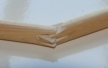
* Beware of dowel that is joined - the joint may not be water proof and can fail in damp conditions! See image below for the method of joining some dowel. The "zig-zag" splice joint can be seen on careful inspection. Hardwood dowel (without these joints) can be obtained from B&Q in the UK.
Assembly
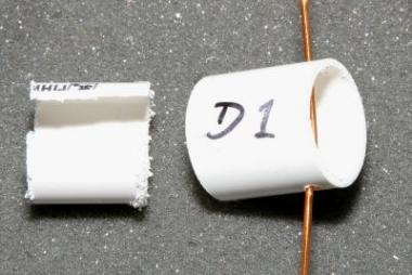
The wires are measured and cut to one inch longer than needed to allow an overlap for joining, for example cut the reflector wire to 248 inches. Thread the corner pieces onto the wire, then scrape the varnish from the end inch of each end of the wire. Overlap the wires by one inch, then grip the overlapped wires with two pairs of pliers and twist the wires together. Secure with solder. Mark the corner pieces "D1", "D2" and "R" to avoid mixing them up when assembling the antenna out in the field.
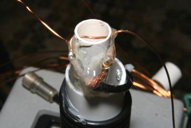
In the case of the driven element, I overlapped the wires through holes drilled in the end of a 6" x 3/4" diameter piece of plastic water pipe leaving a gap between the wires of 1/2". The ends of the wires were then bent over and soldered to a length of RG58 coax. Over the 3/4" pipe I hot melt glued a shorter length of 40mm diameter plastic waste pipe and wound the coax around the pipe to form a coaxial choke balun. 12 turns close spaced on a 40mm former gives a very effective choke for 50 MHz. The coax was secured to the waste pipe with a couple of cable ties (Ty-Raps) and terminated in an SO239 socket. The coax should be sealed with liquid electrical tape to keep water out. In order to obtain a better fit for the corner pieces on the spreader dowels, a short length of plastic waste pipe (the same as used for the corner pieces themselves) was cut lengthwise to remove a section, squeezed and inserted into the corner piece. The corner pieces are approx. 3/4" diameter x 1" long, the inserts are 3/4" long.
Carefully mark out and drill the boom, DO NOT make the distance between each horizontal and vertical hole pair too close otherwise the "L" shaped screw hooks will foul the spreaders. Use a drill stand/press to ensure the holes go through the boom at 90 degrees. Drill pilot holes for screw hooks. Screw the hooks into the boom, then remove them and grind off the point to minimise damage to the spreaders when used to secure them in the boom.
Cut the spreader dowels slightly too long for the wires, fit them into the boom and trim for nice tight wires, without excessive "bowing" of the spreaders. The boom can be planed to an octagonal section in order to reduce wind resistance and weight. Both the dowels and boom should be varnished to protect them from the weather.
Tuning and performance
The antenna was assembled using the dimensions shown above, the SWR was at a minimum around 200 KHz lower than the design frequency, removing one inch from the driven element, and re-soldering it, moved the tuning sufficiently higher in the band for my purposes. Note the tuning will vary slightly with height, if possible test the SWR at the intended operating height. The minimum SWR was approximately 1.2:1, with quite sharp increases as the frequency is changed, which at least indicates it isn't acting as a dummy load. This 4 element quad gives a good match at resonance, measurements on an MFJ 259B antenna analyser read close to 50 Ohms at 50.2 MHz with a 1.2:1 SWR. Built as above, the antenna doesn't cover the whole 6 metre band. As I only use CW and SSB over a small portion of the band it's not an issue to me.
On air performance of the 4 element quad is very impressive, not having an antenna test range I can really only report my findings on a distant beacon. In the forward direction the signal was S7, off the rear S zero but audible. At 90 degrees to the wanted direction the signal could not be detected. While I could quote the signal level required to obtain S7 and speculate what S zero might have been, for all practical purposes the antenna does what I expect it should. Book figures for gain give 10 dB over an isotropic radiator for a 4 element quad. These are theoretical figures and don't necessarily equate to reality. The "free space" figures in EZNEC 4 give a gain of 9.6 dBi and a 26 dB front to back ratio for this antenna.
To pack the wires for transport, twist and loosely fold them, secure with re-usable ties, those ties found in garden centres which are used to secure plants to stakes in the garden are ideal, as they are soft and pliable.
If you have EZNEC, click here for a zipped file of this antenna, alternatively click here for an azimuth plot, or here for the SWR plot (both in free space, not over real ground). EZNEC can be downloaded from here: http://www.eznec.com
Since originally building the quad, I purchased EZNEC and modelled the antenna. The plots and files in the paragraph above are based on the reflector having a circumference of 247 inches. Several other models of quad antennas appear to have a significant notch in the rear lobe when modelled with EZNEC, by increasing the reflector cirumference to 248 inches the front to back ratio should in theory increase significantly. When I built the antenna, attempts to tune a smaller sized reflector by adding a stub didn't appear to offer any advantage over the 247 inch reflector. I've added this comment for the benefit of those who like to experiment. The forward gain doesn't change significantly when one inch is added to the reflector. For a free space plot of this version of the antenna, click here
If you really want to lengthen the boom to 15 foot, the gain will increase by approx 1 dB. By increasing the diameter of the reflector loop the front to back ratio can be maintained. The driven element will need to be slightly shorter for an optimum match. For an EZNEC file of this longer antenna click here. Note I have only modelled it, not built it.
2 element 6m quad - later version based on optimum spacing
The 4 element quad is my favourite antenna for 6m portable use, but there are occasions when it's not worth the effort of assembling the 4 element for the extra 2 or 3 dB of gain. Having previously used a short boom 2 element quad with a gamma match feed, I decided to examine the possibility of a longer boom quad fed with an electrical quarter wave matching section using 75 Ohm coax. For those not familiar with this method of matching, it halves the 100 Ohm nominal feed impedance of the loop giving an impedance close to 50 Ohms at the end of the matching section. The gamma match feed arrangement worked but is potentially lossy and causes the antenna to "squint" by not having a symmetrical radiation pattern.
The dimensions of this 2 element quad were obtained by inputting various loop sizes and spacing in EZnec, the element spacing is 30 inches, the reflector loop is 252 inches (add an extra inch when cutting as per the 4 element instructions above), the driven element is 236.8 inches plus approx 3 inches extra for termination and coax connection. Construction is more or less the same as for the 4 element version. The 44mm square boom is 33 inches long overall.
Wire size is not critical, 14g enamelled copper wire works well. Use bare or enamelled copper wire. The feed arrangement uses an electrical quarter wave matching section comprising approximately 39 inches of 75 Ohm coax (assuming a velocity factor of 0.66). RG59 is OK for the UK power level of 400 Watts and is easily wound through an FT240 sized ferrite ring to form a choke to minimise RF on the outer of the coax. For higher power levels RG11 should be used. The method of determining the correct length of 75 Ohm coax is to terminate one end with a PL259 plug and measure the impedance with the other end open circuit using an antenna analyser. Strip back a couple of inches of insulation and form the ends into pig tails then check the frequency where the antenna analyser reads zero Ohms, you can also use a 100 Ohm resistor across the open end which should read as 50 Ohms on the analyser when the length is a quarter wave. Obviously cut the coax a little longer than needed, measure and trim, etc.
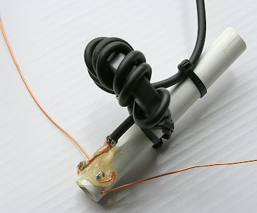
The above illustration shows the feedline choke and 100 Ohm to 50 Ohm matching section, this comprises 8 turns of RG59 coax through an FT240-43 ferrite ring. The open end of the coax is sealed with liquid electrical tape which also holds the connection points to the wire loop firmly in place. If you make a QRO version, the coax will be too thick to wrap through an FT240 sized ferrite ring, so consider slipping a few ferrite sleeves over the RG11 coax to stop RF flowing on the outer of the coax. Some manufacturers suggest that ferrite chokes are not necessary on a quad antenna, but feeding a balanced antenna directly with coax seems wrong to me and a ferrite choke on the feedline does no harm at all.
The SWR measured at the junction of the RG59 matching section and the main 50 Ohm feedline is under 1.2:1 at resonance. The front to back ratio is very good but it is not easy to measure. The EZnec files suggest the front to back ratio at resonance is 23 dB and gain in excess of 7 dBi (in free space). Click here for the EZNec file of this antenna, click here for a plot of the pattern in free space.
White plastic electrical conduit tubing was used for the various corner pieces. Short pieces of tube had a 3/8" slot cut in them, they were then squeezed and inserted into the shorter corner pieces to give a better fit for the dowels. There was no need to glue them in place.
Wood and plastic parts were obtained from B & Q, who stock 12mm hardwood dowel in 2.4 metre lengths. 44mm square section pine was used for the boom. B & Q also stocked the U bolts. 1.25mm enamelled copper wire came from Brocotts on eBay. Liquid electrical tape came from Sotabeams UK
3 element 6m quad
By increasing the spacing between the driven and first director elements on the original 4 ele boom, a 3 element quad can be accommodated. I have not built one, but the model looks fine and would be slightly quicker to assemble for portable use. The EZnec zip file is here and a plot of the free space pattern is here.
The following individuals are thanked for their patience with my many questions on quad antennas.
Brian Hummerstone, G3HBR, LB Cebik, W4RNL (sadly now both SK) and Dale Hunt, WB6BYU
And of course thanks to Markus, VE7CA, for the original idea.


|