

GM3WOJ 50MHz 8877 amplifier page Updated November 2006
Hi - this page has proved much more popular than I expected - please see updated information below :
Remember Plate = Anode, Tube = Valve!
Why build a high-power amplifier for 50MHz ?
I've had a home-made 2 x 4CX250B amplifier for 50MHz since the first day I was active on 6m, but there are many situations where I felt the need for more power (not just more antenna gain!). On 50MHz, as on other bands, most QSOs are propagation dependent - if you are not in the right place at the right time then it does not matter if you are running 10kW you still won't work the DX (you won't hear it anyway) However, for some propagation modes (e.g. auroral reflection) high power will make the difference between making the QSO or not. Having spent a few years gathering the parts (amp. parts are not so easy to source here in the N. of Scotland) I finally had everything needed for an 8877 amp. by early 1999. I decided to use a surplus Philips VHF base-station cabinet - this had been a 700W O/P TX on 151MHz approx., using a bank of 7 x 100W modules + combiner - I had no PSU (50V d.c. at n amps) and it did not look likely that I could easily modify this unit to 144MHz, so the cabinet seemed the most useful part (Mark GM4ISM is putting the PA modules to good use) Using a surplus cabinet/chassis has some disadvantages - holes need to be blanked out and larger components cannot necessarily be positioned exactly where you would want them, etc.
GM3WOJ construction mottos are "Always start a project right away" and "Always do the most difficult or boring part of the construction first" (this is a good motto for a lot of things in life!) - so - I constructed the PSU + control circuits etc. first, leaving the RF deck to last. As it turned out, the anode/plate circuit is the part which has proved most difficult to get to work properly. Each part of the circuit was tested as I went along, so I was reasonably confident that everything would work when switched on together. Total construction time probably was about 50 hours, all in the winter months - some evenings just spending a few minutes looking at part of the circuit. I find it a VERY good plan to 'stop dead' if you encounter a problem or unforeseen difficulty - usually the problem can be solved with a few hours of thought while you are at work, etc, whereas if you continue things often get worse ! Patience is a key factor in amplifier construction.
Constructing an amplifier, whether HF, VHF or UHF, is not a tremendously difficult task - gathering/finding suitable parts is usually the most difficult part. It's amazing how many amateurs have 'parts for an amplifier I'm going to build' but they lie around for years and never get used - please advertise them for sale and someone else will use them ! A major problem with home-construction of amplifiers is that it is difficult to gather components which are of suitable rating/physical size - a commercial amplifier manufacturer works from a design and can source components to fit the available space/layout/required rating - in a home-made amplifier very often one or more of the components is grossly over-rated or far too large for your requirements - as a result home-made amplifiers are, generally speaking, larger physically than commercial amplifiers. You have to take extreme care with the high voltages involved, and develop your own HV safety rules - for example, never trust the front-panel HV meter - always switch off at the mains, watch the HV decay as the smoothing capacitors discharge, then after removing the covers, earth the anode or whatever part of the circuit you are going to work on with a screwdriver before proceeding. One day, you go into your workshop and what was a 'pile of parts' has become a 'useable amplifier' before your very eyes - it's a great feeling !
Which design is best ?
At the 1997 RSGB VHF Convention at Sandown Park I saw the 8877 amp. constructed by Geoff Brown GJ4ICD, and had the opportunity to study the anode circuit briefly. My requirements were slightly different from Geoff's - I wanted more power output, a much bigger blower, and I was not concerned about how much space the amp. took up in the shack. (See http://www.gare.co.uk/gj4icd_8877_amplifier.htm for full details of Geoff's amp. design) Although the amp. I constructed was based loosely on Geoff's design, as things progressed I moved further away from his circuit. One over-riding requirement for my amplifier was that I can modify it (by replacing the anode and cathode circuitry) to be a 160 -10m amplifier at some later date. I used the same diecast box for the grid/cathode circuitry but that's really the only similarity. Some of the circuitry e.g. grid-current trip, was copied from an article by Jerry Pittenger K8RA in 'Ham Radio' magazine - January 1981 entitled 'Modular Linear Amplifier for the high-frequency amateur bands'.
There are various other available designs for 6m amplifiers - using the 3CX800A7, 4CX1000A or 3-500Z tubes, and a variety of plate tuning methods. 50MHz is approaching the limit of a Pi or Pi-L network, and the combination of output capacitance and stray circuit capacitance can approach/exceed that needed as C1, your 'Tune' capacitor. The ARRL handbook has a design which does away with C1, and uses an ingenious 'squeezable' Pi coil. This design is tricky to make mechanically, but gives good efficiency. Another design using the 3-500Z uses a 'shorted turn' - mounted inside the Pi coil, and rotated to vary the inductance of the coil, and hence the tuning. Again a bit difficult mechanically. In 'shorted turn' designs, as the 'shorted turn' is coupled more tightly to the main coil, the total inductance of the coil is reduced, hence the resonant frequency is raised. Another 3CX800A7 amplifier design published by the ARRL uses a conventional Pi-L circuit. A well-designed 6m amplifier will be relatively easy to copy - a poorly-designed 6m amplifier might work for the builder (more by luck than anything else) but will be difficult or impossible to copy - it might be too component-specific, too layout-dependent, or too operating conditions-specific.
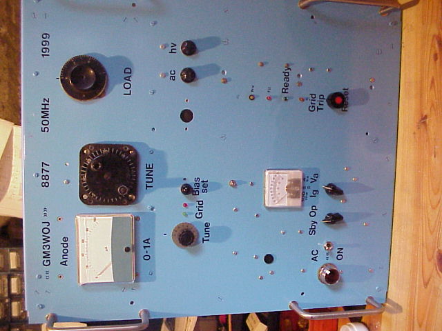
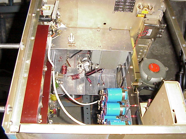
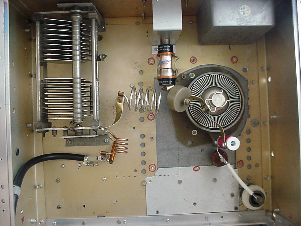
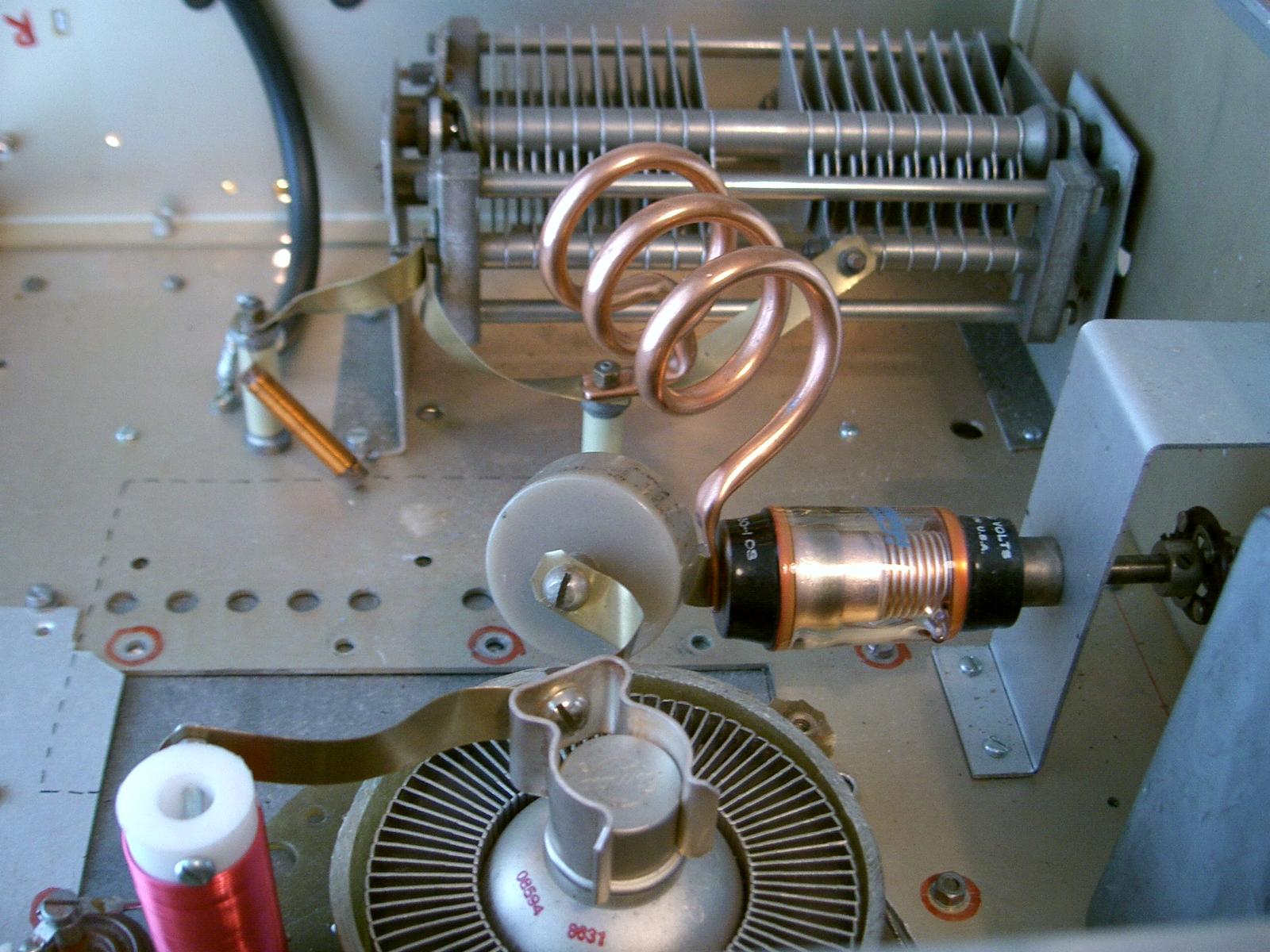
For an enlarged view, click on any of these photos of the amplifier under construction :-
Front panel Upper RF deck Lower RF deck Early (useless 35MHz) Pi-L circuit
Ironically, since finishing the construction of this amplifier, I've received a lot more design info. It would have saved time if I'd done more research before starting the project, but that's a common mistake - get the project started then modify things as you go along - getting started is the key thing.
My friend Dave Tremayne ZL1AV e-mailed me circuits from the 'Radio Handbook' Ch.22 P.38-43 which give details of a 'shorted turn' design by W6UOV. Dave Bowker K1FK has kindly send me a copy of EIMAC Amateur Service Newsletter AS-42 (Reprinted in 'Ham Radio' magazine February 1971) "two-kilowatt linear amplifier for six meters" by W6SAI. These are the same amplifier (identical photos) - using a 'shorted turn' mounted at one end of the plate coil, and pivoted to vary the coupling, and an 'anti-inductance' strap - I think fairly layout-dependent but a design I'm considering changing to for improved efficiency.
Tools and test equipment
No really special tools were used to build this amp. - however you do need : Hand-drill + set of HSS bits 1.5 - 6.25mm, power drill + 3 or 4 larger HSS bits, screwdrivers, pliers, M3 taps + drill, 15W soldering iron, and larger soldering iron - I use an old faithful Weller Soldering Gun 100/150W, small propane hand-torch for soldering brass/copper tube. I use old-fashioned wire-strippers which work well (they look like long-nosed pliers but have 2 v-shaped jaws which grip the wire) and I have 2 or 3 Q-max hole cutters left over from the old B7G/B9A valvebase days! Larger holes are cut using an ordinary electric jig-saw with metal-cutting blade. If you are starting from scratch, you can purchase (although it's becoming very difficult in the UK) ready-made aluminium chassis/boxes. Test equipment is also fairly basic (although I did invest in an L-C meter), an SWR bridge/power meter, old Avometer to read 0-2500V d.c., and Fluke 73 DMM.
June 2006 update - well after 6 years and a trip to and from New Zealand, this amplifier is finally completed and working properly ! About 55W of drive from an FT-650 results in 1500W o/p. Grid and Anode tuning are stable and smooth. I finally had time to duplicate the anode coil described in the original GJ4ICD article i.e. 3 turns, 1.25" inside diameter, about 2.5" long, wound with 0.25" copper tubing - about 260nH = 0.26mH. My conclusion is that the anode circuit is not so critical as I originally thought, but you will have to experiment with values to suit your own physical layout of components.
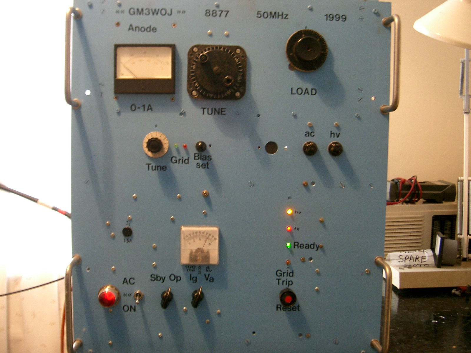
For an enlarged view, click on any of these photos of the finished working amplifier :

Good luck with your amplifier construction project ! 73 Chris GM3WOJ 20th June 2006
------------------------------------------------------------------------------------------
In May 2000 I posted the following request for advice to the [email protected] reflector - I've pasted in some of the responses I received below - they make interesting reading :-
I've finally finished a 6m amp. using an 8877, and the output Pi network does not resonate, even with very low values of
inductance, because of (I'm guessing) approx. 25-30 pF of Cout + Cstray. I'm using a 3-30 pF vacuum variable for C1 and
a wide-spaced air variable for C2. Anode load = 2500 ohms approx.
(By the way, I use one of these Almost All Digital Electronics L/C meters, and it's great - here in the UK they are available from
Mainline Surplus Sales +44 870 241 0810 for US $125)
Some advice please - should I modify the Pi tank to either the 'shorted-turn' or the 'adjustable-coil' design ? Both seem a
bit tricky mechanically, with the 'shorted-turn' design probably easier ? Are there any other designs which overcome these excess
capacitance problems ?
I've not completely given up on the Pi-tank - I tried the idea of a small inductor (0.2uH approx.) between the anode blocking
cap. and the tune capacitor (as in the 30S-1) but still not able to resonate the circuit at 50MHz.
There's a lot of hot air in this shack at the moment !
Responses received from the 'amps' e-mail reflector :-
-------------------------------------------------
I use an 8877 on 50 mhz that plays very well....about 2k out with 50 watts in. When I get home this evening, will e-mail you the details on the pi-L
circuit I use. Like you, I use the 3-30 vacuum variable for the plate (C1); I also use a 5-125 vac for the L variable cap, but this cap can be an air
variable. I will try to e-mail you some pics as well of the rf compartment.
Have you checked GJ4ICD web site? I know he has an 8877 on his site for 50mhz.
--------------------------------------
Duplicate the design at http://www.gare.co.uk/gj4icd_8877_amplifier.htm
I have used this design several times, and it worked every time. The plate choke is very critical here...that may be messing up your
anode circuit.
------------------------------------
Eimac Amateur Service Newsletter AN-42, February 1971, has an excellent design for an 8877 amp on 6M using a Pi-network in which the tube
capacitance forms the input capacitor of the Pi-net, and a variable (shorted turn) coil is use as the main TUNE control and 100 pF Pi-net output LOAD
capacitor. I duplicated this amp. in the 70's and it is trouble-free and very easy to get operational and very stable (without neutralization.
-----------------------------------
Junk the pi net. I have built several single and 2 tube 8877 amps for 6m using a knock off of the w6po 2 meter amp. instead of
using pipes for the resonators I used lumped inductors, approx 3 1/2 turns of 3/8 copper tubing on each side with a pair of 100pf blocking
caps on each side if I remember rite the tune cap is about 4" round and the load cap about 4 x 6' square. they tune up just like the low bands,
efficiency if you believe the meters and bird is about 65% , make power comparable to the low bands and once you tune it up you can forget about
it cuz the tuning does not drift. I just left 6m after 43 years on the band , tired of listening to white noise, sold a 2 tube 6m amp to a
fellow in Louisana, it made 5kw out with 150 watts drive. if the band ever opens to
UK again I bet you hear it.
----------------------------------------
I have implemented a version of the GJ4ICD amplifier and mine doesn't work right either....
With mine the anode circuit tunes okay, the 30pf vac variable is almost exactly half meshed... but at high power the output load capacitor ends
up fully meshed at around 1500W out and then I get a significant onset of grid current.
So, basically I can't get enough loading capacitance. I used the CAV 75 37 capacitor suggested by Geoff GJ4ICD but found it
to be physically much larger than the one he actually used in his own amp. Its also mounted on the base of the anode box. With the shaft protruding
through the front panel it 'bit' me on one occasion when running high power and tuning it up.
Considered opinion is that the loading cap has too much self-inductance (maybe only 5-10nH) and is self defeating.
I have even added a HT58 50pF cap from the end of the anode tank (loading cap end) to ground but the loading cap still ends up fully meshed.
Finally (last week) got a smaller 73-1-145-25 cap from RF Parts, its half the physical size (length), 20-240pF at 2000V, and installed it on
the basis that I could fit the tank circuit better and it would have less self-inductance - its made things worse... I can now only get about
1200W out with 3500V on the anode at 800mA - efficiency has dropped...I'm wondering what to do next... if only I had a network analyzer...
------------------------------------
Forgot to tell you of another website you may find helpful (www.mbn.net/kd9jq/hamradio/kd9jq.html
= broken link)
This site has amp design free-ware that is excellent for what you're doing. Go to his software download area and download the "Triode" program.
It will tell you exactly the values you need for given power out/in, anode voltages etc.
I also forgot to venture an opinion on the shorted turn and adjustable coil: you don't need to go there unless you just like to build mechanical stuff. I
guarantee the pi net or pi-L will work. If you think of it, I'd like to know your no-load and full load anode
voltage; would also like to know about your plate RF choke and the filament choke.
-----------------------------------
Duplicate the circuit at http://www.gare.co.uk/gj4icd_8877_amplifier.htm
....It works great!!! My 8877 does 2000 watts output on six with that
design....my anode voltage is 3700 volts. Be sure your tuned input network is
similar also. That design is the best I have seen. I had a lot of problems with the
shorted turn design, I abandoned that method for the one at the link.
----------------------------------------------
I've just got dragged in to trying to fix an amp which is a 'chinese' copy of the ICD design, and which won't tune nicely. What supply voltage and
power do you run at?
My initial look came up with two points - the Cout of the tube imposes quite a high network loaded Q and the physically large loading cap used in the one
I'm going to try and fix is probably above self resonance at 50MHz, and acting as a variable shunt inductor.
When I get it on the bench, I'll report on what the network analyser indicates. Chris - if you have the gear, put 2k2 from anode to ground and sweep the
aerial input to see where it's doing the matching.
------------------------------------------------
I looked at the photo on your www page, and my first impression is that this is a tank circuit for 15M-10M at best. There appears to be way too much
inductance in the tank coil for 6M. The output capacitance of the 8877
plus stray capacitance of the tube and strapping to the chassis, etc., in my
opinion, is probably providing in excess of 30 pF, in addition to the capacitance with the vacuum variable.
I highly recommend you consider converting to the Eimac recommended circuit and layout, omitting the TUNE vacuum variable, and allowing the tube output
capacitance and stray capacitance form a fixed "tune" capacitance for
the tank circuit and use a shorted turn to resonate the tank coil.
----------------------------------------------
I found that when running GG-VHF/UHF amplifiers the efficiency is very much related to the input circuit and
the components used there, since this circuit is "in series" with the plate
circuit DC and partly signalwise.
-----------------------------------------------
I used a 3-30 pf vac var in my 8877 6M amp, I used a 10M coil from a B&W 850
as the tank coil. there are pics of the pi-net and under the chassis on my web page below. runs 1750-1800 watts out with 3000 volts under load.
-------------------------------------------
Layout on 6 meters IS VERY CRITICAL when using lumped constant Pi-network components, and there can be no compromises at this freq. The
layout of the plate tank circuit, plate RF choke, plate blocking capacitor, tube, and tank coil are absolutely and
peculiarly critical in order to be optimized for 6M. Large distances between components will only cause
instability and the inability to obtain optimum efficiency.
-----------------------------------------
the original used a wide spaced air variable so that doesn't seem to be the
problem. My anode tune vac varable is a physically very small Jennings and the straps used on the anode line are all very
wide. I also used the same boxes specified on the first amp and identical dimensions for the
anode compartment on the second. Other than that I can't think of anything. I run mine with 3.7kV on load and the efficiency is very close to 65 %.The
thermal stability is superb as well, the amp never needs retuning from day to day.
------------------------------------------
Specifically, if the choke isn't acting like a choke, the tuned circuit will see it as another inductance
which is in parallel to RF ground (the bypass capacitor) with the other components in the tuned circuit.
This would, of course, throw the resonance of the plate circuit off to another unwanted frequency. I would suggest
adding turns to your choke after you're satisfied that the problem might lie there.
Another possibility is your plate blocking capacitor. If the capacitor is open, there will be little or no
coupling to the tuned circuit and, thus, minimal to no effect when you adjust the capacitors. I and others
have run into this problem, too.
---------------------------------------
The tank coil is way off. To keep the losses low it needs to be big. I use 2.5 turns of 6mm copper tube 2.5 in diameter. Vacuum C tunes at around
12-14pF.I use a 200pF loading C, tunes at around 120pF.
You will not get good harmonic rejection with a simple L. I use a Pi-L, the second inductor is 8 turns 1 inch diameter spaced by the wire diameter.
The loading C is just as critical as the tune C Bolt all the connections and hard solder.
Keep the blocking C and everything else out of the airflow!
Iq = 100mA
50W in = 1800W out at 3800V. Ig = 40mA
80W in = 2500W out at 3700V . Ig = 70mA
2nd harmonic -65dB all others >-80dB
---------------------------------
Anode volts 4000
Anode amps 1.25
Grid current 140mA
Drive power 100 watts
Output power 3400 watts
Anode dissapation 1600 watts
Apparent efficiency 68 %
This is what happens without exceeding the tubes ratings
Anode volts 3800
Anode amps 0.95
Grid current 80ma
Drive power 55 watts
Output power 2450 watts
Anode dissapation 1160 watts
In other words you should be able to do 2.5 out without exceeding the tubes
ratings.I can still see better IMD than the prime mover at this output
level.
----------------------------------
There has been a complete 8877 design in QST years ago for 6 mtrs with a
stripline by a guy Meade (second name ). He also designed a 2 meter amp.
Have no time to find the article right now, It may also have been in one of the
ARRL handbooks.
------------------------------------
With the lid off the amp its 23pF and lid on its 29pF. There was
no problem with the anode choke or EHT bypass cap at all - this appears to be a
red herring. We put a 50Ohm load on the antenna socket and probed the
anode with network analyser and tuned for a resistive match. With the output cap
fully meshed and the tune cap set for resonance at 50MHz we got 2200 ohms. The
match range was 400 to 2200 ohms.
Took out the tank coil and measured it - 240nH - maths etc. - decided it was too
small and we need more like 300nH. Made a 4 turn coil and fitted - this
measured 290nH.
Network analyser now shows match range 900 - 3700 ohms when probing the anode.
Re fit all parts and tune up: 50W drive - 3300v anode - 40mA grid - 900mA anode
- gets 1600 watts output and the load cap is 2/3 meshed. The anode tune
vac variable used to mesh about 70% closed - its now only about 20% closed due
to the increased L. Anode efficiency was (before) at around 62-63% and has
now dropped to more like 55% - this is apparently a good thing since too much
efficiency in a 8877 amp means we're running too far up the compression curve
and its not a linear amp... In summary - a significant improvement- the
input match is still poor at about 1.8:1 and needs some work though.
------------------------------------