| DIGITAL AMATEUR RADIO EMERGENCY NETWORK of West Virginia (DAREN) 145.690 Mcs. |
||
| Lightening by Ray W3JIW | ||
| LIGHTENING FREQUENCY
Photometric observations from the orbiting solar observatory satellite OSO-2 showed ten times as many lightning storms occurred over land as over the ocean. It was learned that the North Atlantic Ocean has more lightning storms than similar areas of other oceans. Few lightning storms occur over desert regions, according to satellite findings. One of the most active lightning regions in the world is Java and in the United States-Central Florida holds that distinction. There is a popular misconception that lightning never strikes twice in the same place when in fact it frequently does. The Empire State Building in New York City is a good example of repetitive strikes having been struck as many as 48 time in one year. The assumption that the pulse rises to maximum value in 1.2 micro-seconds and in 50 micro-seconds the impulse will have fallen to 50% of the crew or maximum voltage. The flash we see is actually a return stroke from earth to cloud at a speed of 100 million feet per second or about 100,000 times as fast as sound, completed in one tenthousandth of a second. The
eye cannot distinguish it other than a downward stroke. Space
technology
with high speed camera have allowed us a better look at the step leader
or pilot streamer. A bolt can have a potential as high as
15,000,000
volts and deliver an average of 5,000 to 20,000 amperes to its
path.
At Cape Kennedy a recorded peak of 100,000 amperes on a strike to a
launch
tower in 1971. It is no wonder, then, that its explosive force can
demolish
a tree or otherwise severely damage property. The Tree explodes
when
the water and other substances in it are vaporized.
TABLE I |
||
| TOWER
GROUNDING
CONDUCTOR
A common practice is to use copper wire attached to a galvanized tower leg or guy wire anchor. Also joining a pure copper grounding conductor to the zinc-covered steel will produce an unwanted electrolysis action which in fact washes away the zinc coating. So the ensuing corrosion will shortly result in a poor connection or even an open circuit. Painting or coating will stop such an action. ONLY IF ALL MOISTURE AND AIR are depleted under the coating. You can use a buffer metal such as bronze, stainless steel, or brass. Or better yet use an exothermic welding process. A widely used method is known as CADWELD (r) this is the TM of Erico Products Inc., 34600 Solon Road, Cleveland, OH, phone (216) 248-0100. The molds to use in the application are Graphite and reusable for many connections. However these molds are not cheap currently they probable exceed $50.00. This process provides de-oxidized molten copper which mixes with the upper zinc coating or steel to form an air tight connection of the conductor to the other metal part. Some favor the addition of a copper down conductor running down the length of the tower. The idea recognizes that resistance between tower sections averages about .01 ohm. Thus a bolt could cause a large voltage drop. This is largely overridden by the inductive voltage drop which far exceeds the resistance drop. Also the tower inductance is much smaller than any copper conductor. The tower has a much larger conductive surface and is not subject to the large inductive effect due to skin effect on the small conductor. From this the copper conductor effect is really nil. Another detrimental factor is the potential electrolytic effect. If the copper contacts the tower and you have moisture it cause the galvanizing to wash off. Another excuse for using such a conductor is to minimize NOISE and EMI (Electromagnetic Impulse)/RFI (Radio Frequency Interference) problems. When lightning strikes a tower, it has little or no effect on a normal joint. If a tower has been up for many years many joints have become oxidized. If winds have not moved the tower enough to clean bolted connections or if the joints are loose, noise can result. Regular small discharges of lightning to a tower can increase the resistance. A tower down conductor is a quick fix?? It may eliminate some of the noise but It doesn't cure mechanical problems. And it will not prevent joint arcing during a strike. A real fix is to have tower crew loosen every bolt slightly and re-tighten. Afterwards paint or seal all bolts, nuts, and joints. Make sure not water will be encapsulated by the sealant. I used to use a Propane Torch drive the moisture out prior to sealing. |
||
| TOWER
GROUND
CONNECTION LOCATION
Bends with a radius of less than 8" increases the inductance of any conductor. My personal preference is a minimum radius of 12". The important idea is that right angle bends and short radii can cause problems. However the some trade offs can be even worse. Let us suppose that we had a tapered base tower and the ground rod is 24 inches from the concrete base pad. Your choices are:
|
||
| CONDUCTORS
AND ROUTING
When we speak of conductors it is important to remember to use ONLY SOLID Conductor!! I have referred to #2/0 as a size often used. This is useful in many areas. However there is another very useful conductor, copper strap. Even though strap as thin as 1/64 inch it is still useful. A thicker strap is only useful to ease the problem of connection. Here we must find out about "Skin Effect". The current only penetrates to a depth of a few thousands of an inch in any conductor due to "skin effect". Here the inductance of the conductors rears it ugly head. The routing of any of the conductors becomes important. You must also remember the braid of the coax line is a conductor. Always run the coax down inside of the tower. Of course it must be suitably mechanically supported. If you run any other conductor down the tower KEEP IT INSIDE the tower. Now you ask why. If they are placed outside the tower you now have the inductance of the tower and the conductor in parallel. When the magnetic fields are separated the individual conductors now have an increased inductance. This might not be all bad as it limits the current to earth. However the current may take a different path also. BE ABSOLUTELY SURE THAT NO CONDUCTOR FOR LIGHTNING PROTECTION PASSES THROUGH A SHORTED TURN. Let's talk about shorted turns. If a conductor is fed through any length of Metal Conduit or Pipe that is a shorted turn!! Even a hole cutout for a conduit in a Metal Box is a shorted turn! Now back to conductors. The use of straps for connecting ground rods are very useful. An old rule of thumb for the width of copper strap that is 1% of the length of conductor you are going to use. For example a 20' length should have a width of 2.4". It must be remembered that you will have to use a thicker strap on both sides of the conductor for strength where you are attaching ground rods to the equipment. |
||
| GROUND
SYSTEMS:
I must assume you have some control of the Ground System associated with the tower in question. Unfortunately most repeaters are placed on existing towers through the generosity of its owner. It was probably installed by a contractor. Usually they were not given a detailed plan of installation!! All grounding depends on the earth involved. Any ground system must be considered as a large ball of earth. It is used to dissipate the energy from a bolt of lightning by converting it to heat in the bulk resistance. This is a measurable value called "Bulk Resistance". Where we are referring the Ohmic resistance of a centimeter cube. Remember we are dealing with a cube of soil that has a one centimeter dimension on all sides. We also suppose the soil somewhat uniform in its average resistance. The only possible improvement in a Ground System is to enlarge the so called ball. This also has its limits. We can improve a system by using an interconnected array of Ground Rods around the base of the tower. It is very important that the conductors for the multiple Ground Rods be of low inductance and resistance. Here a suitable copper strap is the best. I am not including details on the arrangement of grounds. Ground rods come in many sizes and lengths. The more common ones are 1/2, and 5/8 inches in diameter. They comes in steel with galvanized, stainless, or copper clads. A common length is eight feet. At your home station. The top end of a ground rod should be below the surface of the earth to about the frost line limit. You can improve the situation by using one of the foam type insulations. Then use a piece of outdoor plywood to cover the fragile foam insulation. Why would this be necessary? If the rod is a good conduction of heat it is also a good conductor of cold. The ground rod you thought was so good, could have a sheath of ice along its length. The resistance of ice is about 30,000 ohms/cm cube. Yes ice formation drives the minerals in the water to the zone that was the last to freeze. Therefore you have a high resistance ground. Some may question the need because lightning is no problem in the winter. You better think again. Many fellows find unusual RF Feedback Problems in winter. I must repeat the importance of copper strap with the lowered inductance The steepness of the wave front from a bolt of lightning is the same as a high frequency alternating current (RF) in its behavior. This behavior results in most of the current flowing on the surface of the conductor. The common wire conductor is #2 AWG (American Wire Gauge) stranded copper. However #2 solid copper is much preferred. If you are using #2 solid copper it is equivalent to a strap 13/16" wide. This means the effective resistance is of less than one seventh of a copper strap. It is important to remember that if you are connecting a ground rod to a metal strap it is necessary to reenforce that point. Use lengths of heavy copper strap on each side of the strap then clamp in position. Of course Brazing or Silver Solder is preferred to a mechanical connection or clamp. Most clamps are as useful as a Politicians Promise. |
||
| SOME
TABLES
OF INTEREST
TABLES APPLYING TO GROUND RODS AND SOIL RESISTIVITY.
TABLES APPLYING TO GROUND RODS AND SOIL RESISTIVITY.
TABLES APPLYING TO GROUND RODS AND SOIL RESISTIVITY.
|
||
| PLACEMENT
OF ANTENNA
When an antenna is spaced 1/4 Wavelength away from a small tower there is usually no problem. However towers with a large cross section may require a multiple antenna insulation. However some communication with the antenna manufacturer may be needed. Believe it or not a "J" Pole with the radiation part pointed down and its supports grounded to the tower is good. Such an installation with the antenna pointed often eliminates some icing problems. Now you are asking why does this system work? I had been found that lightning can be expected to act as if had a radius. The placement of the rods above and below the antenna gives the lightning somewhere to land instead of the antenna!. Of course you cannot neglect using a strap to properly ground the shield of the coax!! Likewise the tower must have low inductance. This as any other system is not fool proof. But it can reduce the probability. I have said little about the arrangement of ground rods. If I figure a reasonable way to show it as above I will send it later. |
||
| If
you have
questions. Please mail them with a SASE to: Charles Ray Sinem W3JIW, HC-63, BOX 1840, Romney, WV 26757. |
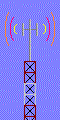 Now
for the antenna location the tower. Never put the antenna on the
TOP MOST PRT of a tower! If you do it is just a Lightning
Rod!.
You must electrically shelter the antenna. This is done by
placing
an array of rods 1/4 wavelength above the tip of the antenna so the
pattern
and radiation will be least affected! This will be several rods
in
a spray pattern. It is assumed that the antenna will be 1/4
Wavelength
from the tower. Then if the rods exceed 1/2 wavelength in length
for the lower frequency in use. We will achieve the desired
effect.
The ends of the rods must not be pointed. The ends of the rods
must
be looped around like an Eye Bolt. A similar arrangement must be
place 1/4 wavelength below the antenna. All to minimize
interfering
with the antennas radiation and reception. If you are using a
single
antenna the tower should be so it is between the antenna and the
direction
that a slight loss of coverage is the least problem.
Now
for the antenna location the tower. Never put the antenna on the
TOP MOST PRT of a tower! If you do it is just a Lightning
Rod!.
You must electrically shelter the antenna. This is done by
placing
an array of rods 1/4 wavelength above the tip of the antenna so the
pattern
and radiation will be least affected! This will be several rods
in
a spray pattern. It is assumed that the antenna will be 1/4
Wavelength
from the tower. Then if the rods exceed 1/2 wavelength in length
for the lower frequency in use. We will achieve the desired
effect.
The ends of the rods must not be pointed. The ends of the rods
must
be looped around like an Eye Bolt. A similar arrangement must be
place 1/4 wavelength below the antenna. All to minimize
interfering
with the antennas radiation and reception. If you are using a
single
antenna the tower should be so it is between the antenna and the
direction
that a slight loss of coverage is the least problem.