
Modified Ground Plane Antenna Adds Second Band
This article presents
the concept of modifying the characteristics of a conventional Ground
Plane Antenna
(GPA) with the elements of an Off-Center Fed (OCF) antenna. Various
configurations provide a simple way
for
multi-band performance and an unusual way to obtain relatively strong
directional gain from a very ordinary vertical antenna.
This combined GPA-OCF principle is presented in a "Table of
Multi-Band Possibilities" covering the range of 6 to 40 meters.
Basics: Center-Fed (CF)
Ground
Plane Vertical Antenna
The “Vertical” part is a quarter-wavelength long radiating monopole. The “Ground Plane” consists of at least two, sometimes three, but typically four radiating elements symmetrically extended to the side. Each element of the ground plane is the same length as the vertical. The antenna is fed where the vertical monopole and ground plane meet hence the term “Center-Fed”.
The impedance is around 35 to 40 ohms when the ground plane is parallel to the ground. By angling the arms of the ground plane downward, the impedance rises. At about 40-45 degrees down angle the impedance matches a 50-ohm coaxial cable. The radiation pattern is a perfect circle. However, if the arms of the ground plane are not RF identical due to unequal length or interaction with nearby objects, the RF concentrates into the most resonant arm(s). The radiation pattern becomes stronger in the direction of greater RF.
Basics: Off-Center-Fed
(OCF) Ground
Plane Vertical Antenna (GPA)
When the ground plane is parallel to the ground, a second way of matching coaxial cable is by feeding the antenna “Off-Center”. As the feed-point is moved from the usual 50% vertical to 50% ground plane ratio, impedance rises. With two radials there is a match when the vertical is 70% and the two radials are 30% of the half-wavelength. With three radials the match ratio is 75% to 25%. With four radials the match ratio is 80% to 20%. Fine tuning can be done by adjusting the ratio or the angle of the radials.
With either method of coax matching, elevation is a consideration. For tuning, be aware that the resonant frequency varies with height. The lowest frequency occurs at one-quarter wavelength. The highest frequency occurs at one-half wavelength. After the highest point the frequency peaks decline steadily at each additional half-wavelength in elevation.
For distance communication (DX), the “Take-off Angle” (TOA) of radiation is lowest when the feed point is a half-wavelength over ground. Each additional half-wave elevation adds another ring of radiation at a higher take-off angle. Feedpoint elevations between each half wavelength have a strong vertical dome of radiation hence are less desirable..
Basics: Combining
Off-Center-Feed
with Center-Feed
A
circular radiation pattern for an elevated vertical antenna requires
only two radials. Interestingly, radials
in pairs are the key to combining Off-Center-Feed with Center-Feed in
an
ordinary ground plane antenna. This simple concept opens the door to
multi-band
operation
Consider a
theoretical
center-fed, 8-meter (37.5 mHz), ground plane antenna with 4-radials. A
half-wavelength is 4 meters long therefore the quarter wave vertical
element is
2-meters long. Each of the radials are
2-meters
long angled downward at 45°.
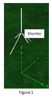

Shorten two opposing radials to be 1-meter long. With the
2- meter vertical element, the resonant half-wavelength is now 3-meters
long (50 mHz) and the two radials are now fed 2/3 to 1/3
off-center. The resonant frequency is higher by 1/3.
Because the 4 radials are not the same length, RF divides between two
resonant frequencies. The antenna is now a dual band 6-meter and
8-meter ground plane. Figure 1.
Lengthen the same two radials to be 3-meters long. With the 2-meter vertical element, the resonant half-wavelength is now 5-meters long (30 mHz) and the two radials are now fed 2/5 to 3/5 off-center. The resonant frequency is lower by 1/5. The antenna is now a dual band 8-meter and 10-meter ground plane. Figure 2.
A common ground plane antenna with four radials can operate on a second frequency
by merely adjusting the length of two opposing radials.
Experimental
To explore this concept, a prototype ground plane antenna (GPA) was constructed using telescoping vertical and radials. The telescoping elements could extend from 8 to 24 inches. The angle of the four radials was adjustable. The antenna was mounted approximately one-half wavelength high on PVC tubing and connected to a Sark-110 antenna analyzer by 9 feet of RG58/U 50 Ohm coaxial cable. Three ferrite “beads” were attached to the coax at the base of the antenna to prevent instabilities by common mode currents that develop from off-center feed. Frequencies used were in the range from 96 mHz to 225 mHz.
The starting
point was to configure a typical GPA with four radials angled downward
at 45°, all the same length as the vertical element, ie.
Center-Fed.
The
Off-Center-Feed (OCF) study was to systematically adjust the length of
two opposing radials and record the development and characteristics of
the second frequency. Because of the wide frequency range
involved and the physical limits of the telescoping elements, these
data were taken in two stages:
- First, by starting at a lower frequency (96 mHz) while
reducing the length of the radials to produce higher frequencies.
- Second, by starting at a higher frequency (225 mHz) while
increasing the length of the radials to produce lower frequencies.
Results
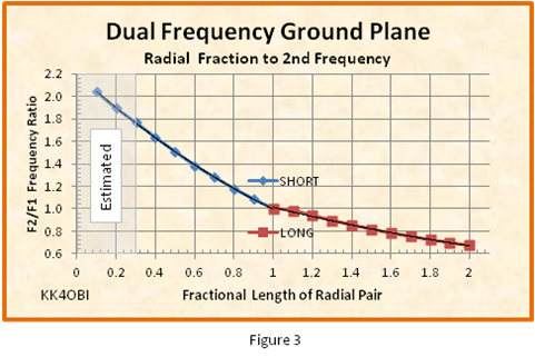
In both stages, length was changed by intervals of one-tenth of the initial length: Short= 1.0, 0.9, 0.8, etc. Long= 1.0, 1.1, 1.2, etc. Combining the two results produces a table of frequencies corresponding to the fractional length of the radial pair from 2.0 to 0.1 times the initial length (1.0). To generalize these data for practical use, the experimental frequencies found (F2) were converted to frequency ratio (F2/F1) from 0.6 to 2.2 relative to the initial frequency of the GPA (F1). See Figure 3 below.
Practical
Use Questions
Q.
I have a 6 meter (F1) ground plane antenna. Can it also be used
on 2 meters?
What is the ratio F2/F1 Frequency
Ratio? F2 = 144 MHz. F1 = 52 MHz. 144/52=2.77. Too
high. The answer is no.
Q.
Can the 6 meter (F1) ground plane antenna be used on 10 meters?
What is the ratio F2/F1 Frequency
Ratio? F2 = 28 MHz. F1 = 52 MHz. 28/52=0.54. Too
low. The answer is no.
Q.
Then how about a 10 meter (F1) ground plane on 12 meters? F2/F1 =
24.9/28.4 = 0.88. Yes
Q.
Or 15 meters? 21.2/28.4 = 0.75. Yes
As can be seen in Figure 3, there are two different curves depending on
whether the radials are being shortened or lengthened.
When
the radials are lengthened the amount of change is abruptly less.
The slope of the curve becomes shallower. Note also the
discontinuity between 1.0 and 1.2 Fractional Length. In this
range there is not enough change to clearly separate the second
frequency, F2, from the initial frequency, F1. This throws the F1
slightly off frequency.
Rule:
When lengthening a Radial Pair the increase in Fractional Length should
be 1.2 or greater.
Table of Multiband Possibilities
Frequency obtained by using F2/F1 Frequency Ratio or Radial Length adjustment
Greyed
areas are impractical and should be avoided
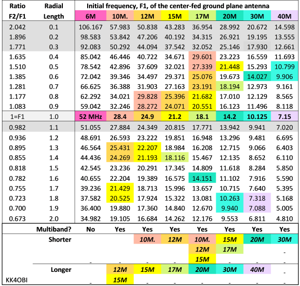
It is posible to both lengthen and shorten pairs of radials. This gives two widely spaced bands. For example a 30 meter GPA can become a 20 meter and 40 meter antenna by lengthening one pair of radials by around 1.8 and shortening the other pair by around 0.6.
By using the ratios or radial lengths from table above it can be seen that;
- a 20 meter GPA can become a dual 30 meter and 17 or 15 meter GPA.
- a 17 meter GPA can become a dual 20 meter and 15, 12 or 10 meter GPA.
- a 15 meter GPA can become a dual 17 meter and 12 meter GPA.
- a 12 meter GPA can become a dual 15 meter and 10 meter GPA.
Just about any length of a conductor can be shaped and adjusted to the radiate the radio frequency (RF) output from a transmitter. Judging how well it radiates and how it could be made better are the eternal questions. Methods such as field strength meters and A-B switching between reference antennas are complemented by computer modeling which can numerically characterize and visualize RF radiation. In the antenna just described, modeling is particularly useful in coming to terms with the relatively complex interactions revealed from the manipulations of the prototype antenna.
For this unusual set of requirements, an antenna model1 using 4NEC2 software2 was developed utilizing spherical geometry. This allows numerous radiating elements each with the unique ability to be positioned at any compass heading and any angle up or down as well as being of different lengths or at any off-center feed ratio.
Basics: The Model
What does the manipulation of two opposing radials do to the radiation pattern of a center-fed ground plane antenna?
 To
study this question a 100 mHz ground plane antenna model was created
with a quarter-wave vertical and four opposing radials of the same
length, in other words, center-fed.
To
study this question a 100 mHz ground plane antenna model was created
with a quarter-wave vertical and four opposing radials of the same
length, in other words, center-fed. Conditions: #14 AWG elements; feedpoint elevation optimized at ½-wavelength over “real ground”; “Auto-segmentation on” to adjust for the varying length of radials; radials angled downward at 45°.
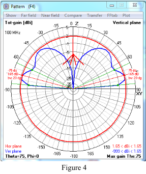
F1 characteristics at 100 mHz are reported as:
Z Ohms = 49.9
SWR = 1.00
Gain = 1.65 dBi
Take-off angle (red lines) = 15°
Half Power Beamwidth (green lines) = 5° to 35°
See polar radiation graph, Figure 4.
The F1 initial tuned frequency of 100 mHz only occurs at one point, when all four radials are the same length*, Radial Ratio = 1. In other words, this is the only time when the antenna is a simple ground plane antenna with the RF current in the lower part distributed equally four ways. At any other time the system functions as two antennas with two of the radials off-center fed at some frequency other than 100 mHz.
|
* With precise modeling, the length of the vertical in a ground plane antenna is never quite as long as the radials which are capacity coupled with ground. However for simplicity of concept, the premise of this study is to start with all elements being the same length. |
Effects of Variable Length Radials
The study is to systematically change the length of the Variable Radials. The Radial Ratio varies from 0.1 to 2.0 times the length of the vertical element using steps of 0.1. All radials are angled at 45°. The results were recorded for the Gain, mHz frequency and SWR.
First, what happens to the antenna's primary frequency of 100 mHz (F1) as the Radial Ratio is changed? The answer: "There is very little change". See Figure 5 below.
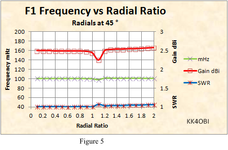
Gain (Red line, square marker) is basically flat varying only by the dip seen at the 1.1 Ratio. This is where the 0.1 additional length is not sufficient to produce a second distinct frequency.
Frequency mHz (Green line, X marker) shows only a slight rise. When the variable radials are shortened, the initial 100 mHz rises about 0.6 mHz higher near Radial Ratio =1 and immediately rises to 0.9 mHz higher. When radials are lengthened, the initial 100 mHz starts at 1.9 mHz higher near Radial Ratio =1 and tapers down to 1.2 mHz higher at the longest configuration.
SWR (Blue line, asterisk marker) is unchanged in the shorter ratios and rises slightly in the longer configurations. The bump at 1.1 Ratio is where the additional length is not sufficient to produce a second distinct frequency.
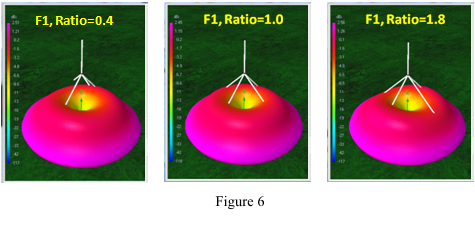
Far Field Radiation Pattern (Figure 6) is not effected as the length of the variable radials is changed from 0.4 to 1.8 Ratio.
Off-Center Feed Impedance
In general a radiating wire can be fed at any point off-center without affecting the resonant frequency. The exception occurs very near the ends. At the center of the wire the RF radiation on both sides is equal. In this balanced condition impedance is lowest and there is minimum RF reflected back on the feed line. When feeding off-center, the both impedance and RF reflection increase due to unbalanced RF in the two arms.
Because of the unusual nature of the dual frequency GPA the usual off-center impedance graphs do not apply.
To remedy this lack of information a model for a vertical wire with a 45 degree bend was developed. The length of the bent lower part of antenna systematically adjusted according to the radial-to-vertical ratio seen in Figure 5. For each adjustment in radial ratio the model found a new resonant frequency. The resulting antenna characteristics were recorded for each point and the range of Z Ohm impedance values were normalized to the lowest value. Thus generalized, a graph can then be used to estimate impedance points of any similar OCF antenna. See Figure 7 below.
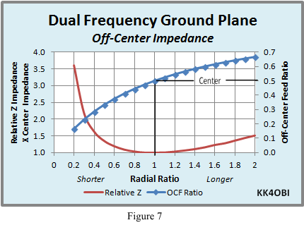
Looking at the Relative Z Impedance line (red line) it can be seen that adjusting the Radial Ratio up to 0.4 times shorter or up to 2 times longer than the vertical will produce desirable Relative Z Impedance values… no higher than about 1.5 times the center impedance.
An example:
If the ground plane achieves a center-fed impedance of 56 ohms before changing the length of two radials, it can be expected that the off-center impedance will rise no higher than about 1.5 x 56 = 84 ohms. This corresponds to a SWR50 of 84/50 = 1.68:1.
When OCF antennas are discussed we commonly hear terms about the feed point ratio such as: “one-third from the end”, or “1/3 -2/3”, or “0.33-0.67”. For this, Figure 7 has a convenient Off-Center Feed Ratio graph (Blue diamond line) related to the Radial Ratio. Notice that the OCF Ratio changes very slowly above Center.
Consider vertical length = 1: When the Radial Ratio length is 2 times the vertical length, the total radial+vertical length is 3, therefore the Off-Center Feed point is at 2/3… or 0.67 on the graph.
Conversely: when the Radial Ratio length is 0.5 times the vertical length, the total radial+vertical length is 1.5 therefore the Off-Center Feed point is 0.5/1.5 = 1/3… or 0.33 on the graph.
Modeling Off-Center Feed
When center-fed and off-center-fed antennas are combined the simple relationship in Figure 7 is only a guide to what is happening. However, more complex sum and difference harmonic interactions exist. To better follow what happens, the 4NEC2 antenna model was used was to vary the length (frequency) of the Variable Radials by a Radial Ratio from 0.1 to 2.0 times the length of the vertical element. The OCF results for Frequency MHz, Gain dBi and SWR were recorded at each new F2 frequency created by the change in length. See Figure 8.
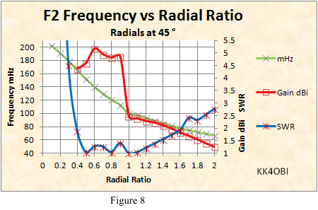
The predicted Frequency mHz curve (Green line, X marker) is no surprise and agrees with the curve in Figure 3 which was derived from the experimental work with the prototype ground plane antenna.
As expected from Figure 8, the high impedance of short Radial Ratios causes the SWR (Blue line, asterisk marker) to become excessive (over 40:1 at 0.1 Radial Ratio). This is in good agreement with results from the prototype antenna work where studies below 0.4 Radial Ratio were terminated because of high SWR.
However, instead of seeing a smooth SWR curve mirroring the smooth impedance curve in Figure 7, interactive bumps are apparent at 0.6 as well at 0.9 ratios. Also the SWR line does not have the usual smooth rising curve above 1.0 Radial Ratio. Instead, it goes upward almost straight diagonally.
Similarly, the Gain (Red line, square marker) rapidly climbs from 0.4 Radial Ratio to around 5 dBi but falls in almost a straight slant when nearing the 1.0 Radial Ratio. Something is causing these unexpected results.
The rise in Gain means a change in the typical circular radiation pattern of a vertical antenna. To compare the 3D changes in appearance as seen from the same angle as in Figure 6, see Figure 9 below. It provides a detailed look at Radial Ratios of 0.4, 0.6 and 0.8 for:
- 3D Far Field Radiation Patterns
- Magnitude of Currents
- Frequency Sweeps
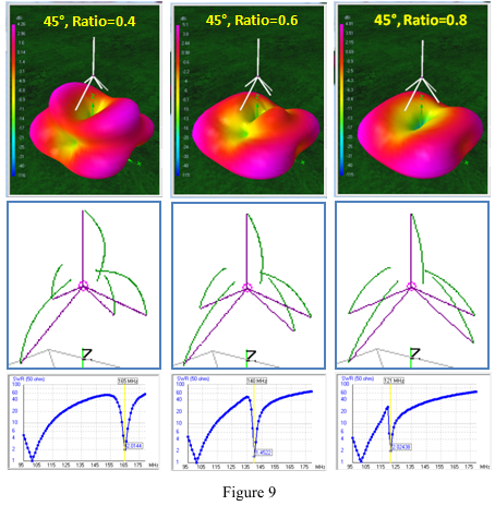 1.0 Radial Ratio = 100 mHz or 1.0 half wave (F1)
0.4 Radial Ratio = 165 mHz or 1.65 half wave
0.6 Radial Ratio = 140 mHz or 1.4 half wave
0.8 Radial Ratio = 120 mHz or 1.2 half wave
The high angle ground radiation pattern is due to the half wave elevation of the second frequency, F2.
Recall that the 100 mHz antenna model is set at ½ wavelength over ground.
Recall also “Feedpoint elevations between each half wavelength have a strong vertical dome of radiation hence are less desirable”.
- Look at Ratio=0.4. Note that the 3D picture has
boat-shaped radiation above
the lower pattern. That radiation is ground reflection
between half wavelengths. It gradually merges downward as the 0.6 and
0.8 Ratios approach one half wavelength elevation.
- The second thing noticed is that the low angle part of the
radiation pattern is rectangular.
The shape causes gain. The highest gain is around 5 dBi which is
indicated by purple color.
Horizontal and Vertical Components
The 4NEC2 antenna modeling software provides the means to view independently the horizontal and vertical components that make the total radiation pattern. Figure 10 below shows these three radiations for the 45°, Ratio=0.8 configuration.
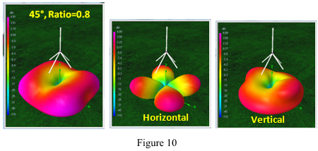
The combined Total radiation pattern on the left picture has more gain than either of the other two as seen by the purple coloration on the corners between radials.
The four lobe Horizontal radiation pattern in the center picture is the common characteristic of this antenna whenever two frequencies develop. Each lobe is formed between each pair of radials and has a take-off-angle of 20°. The lobes remain relatively unchanged no matter what the second frequency, F2, may be.
The low angle circular portion of the Vertical radiation pattern in the right picture is typical of a ground plane antenna. The bulges at higher angle depend on the frequency difference created by the second frequency. As pointed out above, this 0.8 ratio is 120 mHz or 1.2 half wave. As the ratio approaches 0.9 the frequency is 113 mHz or 1.1 half wave causing the bulge to further merge into the lower lobe. At a ratio of 1 the antenna is a single frequency, 100 Hz ground plane with the half wave pattern as seen in Figure 6.
This phenomenon is strictly a function of two different frequencies created from a combined CF and OCF antenna.
A different but similar phenomenon is related to antenna feed point elevation and ground reflectivity
Antenna Feedpoint Elevation
The perfect height for an antenna is when fed at one half of the ground reflected wavelength. This is the balance point with the least upward radiation and the most lateral radiation. In contrast, the poorest height is between each half wave where the most upward radiation occurs. This applies to all antennas but the unusual radiation patterns in Figure 10 created by dual frequency need to be differentiated from the unusual radiation patterns created by elevation.
From Figure 10 above we select the 45°, Ratio=0.8 “3D Far Field Radiation Pattern” for study. We will look at how it changes with increasing elevation in Figure 11 below.
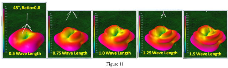
All modeling discussed so far uses a perfect half wave elevation. However, for this study the elevation at 0.5 Wave Length will be increased in steps of 0.25 wave length to “see” the changes in the dual frequency radiation pattern.
At 0.75 Wave Length there is a dome of ground reflected radiation rising in the center. This similar to the Ratio=0.6 seen in Figure 10 which was caused by a difference in frequency… not by elevation.
As the antenna rises to 1.0 Wave Length the reflection dome enlarges and morphs to form a second lateral lobe at a higher radiation angle.
At 1.25 Wave Length a second reflected radiation dome rises, then gradually expands and flattens to become another higher angle lateral lobe at 1.5 Wave Length.
This dome-to-lobe, dome-to-lobe pattern repeats each half wavelength as antenna elevation increases. Three lobes = three half wavelengths. Four lobes = four half wavelengths, etc. each at progressively higher take-off angles.
Radials at 90°
A conventional ground plane antenna has four radials angled downward at 45°. To keep the dual-frequency concept simple two opposing radials were shortened or lengthened to create the second frequency. The results seen in Figure 8 were good when shortened but not good when lengthened.
Work with the prototype antenna determined that longer variable radials gave a good match for 50 Ohm coaxial cable when adjusted to be around 90°. Concurrent antenna modeling was in general agreement but was not refined enough to accurately predict the highest angles found in the prototype by the antenna analyzer.
To maintain the simplicity concept a follow-up study was made with the variable length radials at 90°. The results are summarized in Figure 12 below.
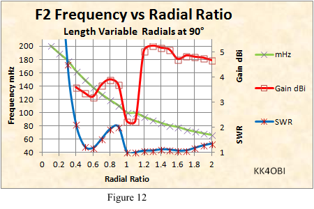
The Frequency mHz curve (Green line, X marker) has virtually no change from that when the radials are at 45° therefore the predicted frequencies of the tables in Figure 4 are good with radials at 90°.
The Gain dBi (Red line, square marker) rises rapidly to around 5 dBi when the radials are lengthened. This is in contrast to the steady fall seen (Figure 8) with the radials at 45°. However, shortened radials are best served at 45° considering the poor results seen above.
SWR (Blue line, asterisk marker) remains remarkably low when the radials are lengthened. It should be noted that the prototype antenna produced the best match with the radials raised above horizontal when the radials were longest.
The conclusion: When shortening the F2 radials, use 45°; when lengthening them, use 90°.
Lengthening Radials
In Figure 12, the rise in Gain (Red line, square marker) means a change in the typical circular radiation pattern of a vertical antenna For comparison Figure 13 below provides 3D views at the same angle as in Figure 7. This provides a detailed look at Radial Ratios of 1.2, 1.6 and 2.0 to see:
- 3D Far Field Radiation Patterns
- Magnitude of Currents
- Frequency Sweeps
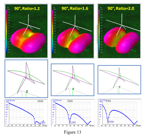
1.0 Radial Ratio = 100 mHz or 1.0 half wave (F1)
1.2 Radial Ratio = 93.4 mHz or 0.93 half wave
1.6 Radial Ratio = 77.9 mHz or 0.78 half wave
2.0 Radial Ratio = 67.1 mHz or 0.67 half wave
The first thing noticed is that the rectangular radiation pattern seen when the radials are shorter, now has become a broad pattern extending from the long (F2) radials.
On the axis of the short (F1) radials, the null becomes deeper as the F2 radials get longer. This is primarily due to the difference between the F1 and F2 frequencies tends to increase the vertical component.
Recall that antenna RF radiation patterns reflected from ground tends to be:
- Lateral at each multiple of a half wavelength over ground
- Have verical components between each half wave
Horizontal and Vertical Polarizations
The 4NEC2 antenna modeling software provides the means to view independently the horizontal and vertical polarizations that make the total antenna radiation pattern. Figure 14 shows how the Horizontal and Vertical radiation patterns make up the "90°, Ratio=1.6" Far Field Radiation Pattern seen in Figure 13 above.
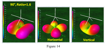
The Horizontal radiation pattern shows the four characteristic F1 lobes between each radial. The lobes are a bit plump compared with those of Figure 10 but exhibit little change in TOA at this unfavorable wavelength elevation over ground.
The OCF Vertical radiation pattern is from the ground plane formed by the vertical and two F2 radials at 90°. The upward TOA is the ground reflection and is controlled by half-wavelength elevation over ground. It is easy to see how these two lobes fit together with the horizontal lobes to form the wide lobes under the long radials.
The Gain is greatest at the corners between radials as indicated by the purple color. The gain under the long radials is the same as the F1 vertical. The net result is a dual frequency GPA with the F2 frequency behaving more like a dipole with around 5 dBi gain but with the nulls broadside rather than off the ends.
VHF and UHF with Gain
As seen in the information presented in the Table of Multi-band Possibilities, dual frequency potential is listed from 40 meters to 10 meters. Below 10 meters the amateur world is replete with dual-band antennas. Here are some examples.
- By reversing the roles played by the radials and vertical there is a commercial 146 – 440 MHz antenna with fixed radials the same length and angle with both a long and a short vertical3.
- A home brew approach is to mount 2-meter and 440 MHz verticals on a SO239 connector along with two pairs of tuned radials4.
- A more technical approach is a decoupling stub on the vertical along with two pairs of tuned radials5.
- A mechanically more complex approach is having two radials with complete sets of four radials for each band6.
Never-the-less, the Combined Center-Fed and Off-Center-Fed Ground Plane technique, as a single frequency ground plane has diversity polarization, a very wide radiation pattern and dipole-like gain. These characteristics could be of interest for mono-band antennas for 144, 222, 440 or higher bands.
For this purpose the radiation pattern with the most uniform gain pattern is desirable. These conditions are best met with an ordinary ground plane antenna with two radials angled 45° down and the opposing radials at 90° which are lengthened by 25%, or a Radial Ratio=1.25.
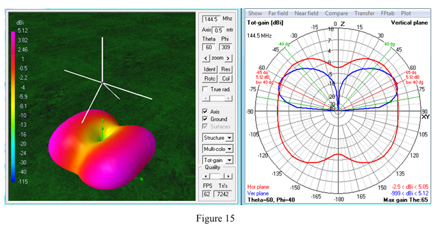
Monoband Modeling
In Figure 15 below:
Gain is a broad 3.5 to 5 dBi in the hemisphere of the long horizontal radials. The half-power horizontal beam width is an impressive 140° of the possible 180° hemisphere.
The nulls are -2 to-3 dBi aligned with the short radials. This makes the antenna behave similarly to a dipole in that the nulls produce a total of 7 to 8 dB reduction in signals coming from the sides of the horizontal radials… just the opposite of a dipole.
Monoband Example
Calculate the length of the elements for this ground plane for 144.5 MHz at Ratio=1.25.
The vertical/radial length calculation, in inches, derived from antenna modeling is: 2643/mHz = inches
In other words: 2643/144.5 mHz = 18.29 inches.
This produces an F1 frequency around 156.5 MHz. The F2 frequency can be adjusted anywhere in the 2 meter band according to the length of the 90° radials.
By adjusting them to be 1.25 longer (18.29” * 1.25 = 22.9”) the second frequency, F2, will be around 144.5 MHz depending on construction details, the thickness of the elements, their velocity factor and antenna feed point elevation
Related to the Table of Multi-Band Possibilities, the F2/F1 Ratio of the example antenna using #14 wire, velocity corrected, at half wavelength feed point elevation is:
144.5/156.5 = 0.923 Radial Length at Radial Ratio = 1.25.
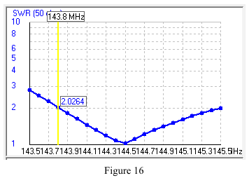
Characteristics at 144.5 mHz:
• Z Ohms: 51.5 +j0.73
• SWR: 1.03
• Gain: 5.12 dBi; Null -2.5 dBi
Band width < 2 SWR: 143.8 to 145.5 mHz (Figure 16)
Vertical and horizontal diversity polarization.
Take-off-angle: 25° with half-power at 10° and 50° above horizontal.
Compared with a dipole the advantages of the Center-fed/OCF ground plane are:
• Low SWR
• 140° beam width versus the dipole’s 80° beam width
• Mixed vertical and horizontal polarization for local communications with dipoles, yagis and repeaters
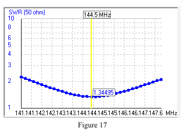
Dipole Characteristics at 144.5 MHz:
• Z Ohms: 67.1 –j2.21
• SWR: 1.34
• Gain: 7.4 dBi; Null -4.9 dBi
Band width < 2 SWR: 141.6 to 147.6 MHz (Figure 17)
Horizontal polarization.
Take-off-angle: 25° with half-power at 15° and 45° above horizontal.
This article introduces the concept of combining the characteristics of a conventional four radial Ground Plane Antenna (GPA) with the elements of an Off-Center Fed (OCF) antenna. It is demonstrated that a second OCF frequency, either higher or lower than the GPA frequency, can be created by Shortening or Lengthening two opposing radials Such a modfication produces no appreciable change in the GPA's radiation characteristics. In this way GPAs for two bands can be created from 10 to 40 meters.
The second frequency does however produces an interesting radiation pattern with considerable gain. This effect can also be used to advantage in the VHF/UFH frequencies to obtain relatively strong directional gain, mono-band performance using this novel form of a GPA.
Reference Links::
1. http://www.qsl.net/kk4obi/Models/KK4OBI%20model%20-%20OCF%20Vertical%204-Radials.html
2. http://www.qsl.net/4nec2/
by Arie Voors.
3. http://www.arrowantennas.com/inst/GP146440.pdf
by Arrow antenna.
4. http://www.hamuniverse.com/na4it2440groundplane.html
by Scott Duckworth
5. www.hocoares.org/images/2005ARRLHandbookDualantennas&jpole.pdf
by Wayde Bartholomew.
6. http://www.diyhamantenna.com/index.php/ham/multiband/dualband-gp-for-2m-and-70cm
by DIY HAM Antenna