
Navigation
Menu
Center-fed Bent-Dipoles
Horizontal Lateral
Vertical
- OCF
Slow-Wave
Other Topics
Home
What
Happens If You...
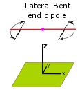
Bend the ends of a dipole to the side?
(rather than up or down)
Bend the ends of a dipole to the side?
(rather than up or down)
The first difference from bending up or down is ground effect. This no longer matters because ends bent to the side are always the same distance above ground.
The other difference is if the ends are bent to the same side or opposite sides. This does matter because there are differences in tuning and radiation direction.
Exactly what happens in these situations is where antenna modeling software provides the answers.
We start with a standardized half-wave dipole made of #14 American Wire Guide AWG copper wire at 1/2 wavelength high fed at the midpoint. The model begins with the resonant length of straight wire and the bend ratio. The ratio sets how long will be the center-fed horizontal section (Ratio of 1 = full length, ratio of 0.5 =half length, etc.). The wire remaining at each end is bent to the side at the defined angle. This reduces gain and changes the resonant frequency to be higher. Retuning to resonance therefore requires a longer wire.
At the bend points think of the arms as having hinges where we can define the any angle of side-bend for the end section. 180 degrees = right angle to right. 90 degrees = straight (no bend). 0 degrees = right angle to left.
The modeling study first determines the operating conditions of the standard, unbent dipole and then progressivly shortens the center section and lengthen the bent ends by steps of 0.1 ratio (10%).
Based on the length of each center section (90%, 80%, etc.), the program intelligently adjusts the length of the straight wire until it converges on the linear resonant wire length that comes as closely as possible to a SWR =1 with lowest reactance (X-in) once in the bent form. This is the optimization function.
4NEC2 Antenna Model: Here
Ends Bent to the Same Side
 This
is an animation of the change in radiation pattern as a dipole is
shortened by bending ends to the side. Gain broadside from the dipole
decreases as you see the pattern become wider.
This
is an animation of the change in radiation pattern as a dipole is
shortened by bending ends to the side. Gain broadside from the dipole
decreases as you see the pattern become wider. There is less than 1dB loss by shortening a dipole to around 50%. This small change is because when are ends are bent, they stay the same distance off the ground
However, more rapid widening (decline in gain and rapid rise in SWR) is seen if the dipole is shortened more than that. Figure 1.
This decrease in performance is easily compensated by bending the ends to opposite sides. Figure 2.
The following graph summarizes the effects on Gain, SWR and Wire Length when the ends are bent to the same side.
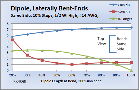
Figure 1
In Figure 1, read from right (no bend) to left.
The Gain (blue line) at 60% is down only 0.36 dBi from the unbent 100% but accelerates past there.
The SWR (red line) starts at 1.37 and approaches 1.0 at 60%. It rises more rapidly past that point exceeding 2.0 at around 36%.
The % Longer (green line) rises gradually to the 3% range, then stays there between 50% and 20%.
The optimum center length for best SWR occurs at the 60% bend point. This is where the laterally bent ends are each 20% of the wire length before bending,
Ends Bent to Opposite Sides
The following graph summarizes the effects on Gain, SWR and increase in Length when the ends are bent to opposite sides. (This requires a change in the antenna model from +Y to -Y geometry in one arm.)
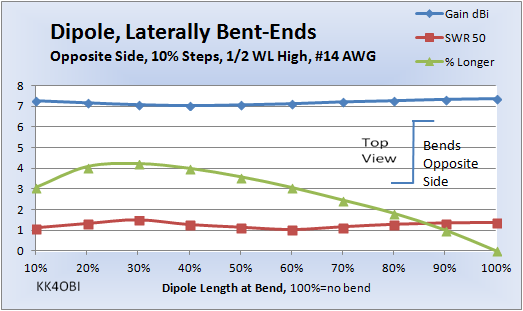
Figure 2
In Figure 2, read from right (no bend) to left.
The Gain (blue line) at 40% is down only slightly, 0.25 dBi, then rises back almost the same amount.
The SWR (red line) starts at 1.37, falls to nearly 1.0 at 60% and 10%, rises to 1.5 at 30% and ends at 1.1.
The % Longer (green line) rises gradually to a maximum of slightly more than 4%, then declines.
The optimum center length for best SWR occurs at the 60% bend point. This is where the laterally bent ends are each 20% of the wire length before bending, In addition, the antenna model shows there is another optimum at 12% where the bent ends are each 44% of the wire length.
An interesting effect, skewing of the far field radiation pattern, becomes more pronounced as the bent arms become longer. The 12% form skews the radiation field 75�, nearly broadside to the bent arms. More on that later.
From the above two graphs it can be seen that a 50 ohm point exists at 60%, same side or opposite side. Questions arise: What happens if you change the angle of bend? Can you tune doing this? What tuning range?
The next studies look at what happens around that area, ie 50%, 60% and 70% dipole length at the bends.
Tuning by Angle of Bend, Same Side
The following graph summarizes the effects on SWR with the bent ends at different angles.
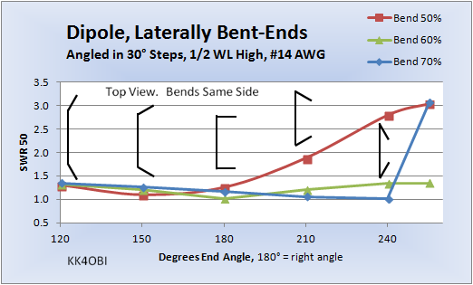
Figure 3
A graphic representation of the angle of bend is shown in black
In Figure 3, as you change the angle of the side bent arms, observe that there is a point around 1.0 SWR for whatever the length of the middle section.
- around 150� angle (exactly 164�) for the red
line.
- at 180� angle for the green line.
- at 240� angle for the blue line.
Rule of Thumb for tuning when at a right angle bend (180�):
If the impedance is greater than 50 Ohms, increase the angle of bend.
If the impedance is less than 50 Ohms, reduce the angle of bend.
Effect of Angle of Bend on Wire Length, Bend Same Side
In Figure 1 we saw only 3-4% increase in length at a right angle bend (180�). However, if the angle of bend is changed for tuning, the length of wire also changes.
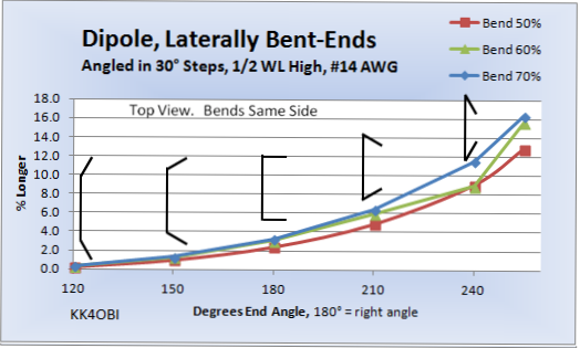
Figure 4
A graphic representation of the angle of bend is shown in black
Figure 4, sumarizesby Degrees of End Angle bend relative to the % Longer wire needed for resonance. This is for where the center section of the antenna is 50%, 60% and 70% bend
.
From the above curves we see now that the increase in resonant length roughly doubles for every 30� increase in angle of bend. Note also, the longer the horizontal straight section, the greater the increase.
Tuning by Angle of Bend, Opposite Sides
The following graph summarizes the effects on SWR with the bent ends at different angles.
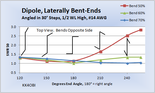
Figure 5
A graphic representation of the angle of bend is shown in black
In Figure 5, observe again three resonant points around 1.0 SWR but somewhat different than in Figure 3.
- around 150� angle (exactly 164�) for the red line. Note how critical the tuning is past 180�.
- at 180� angle for the green line.
- at 240� angle for the blue line.
Rule of Thumb for tuning when at a right angle bend (180�):
If the impedance is greater than 50 Ohms, increase the angle of bend.
If the impedance is less than 50 Ohms, reduce the angle of bend.
Effect of Angle of Bend on Wire Length, Opposite Sides
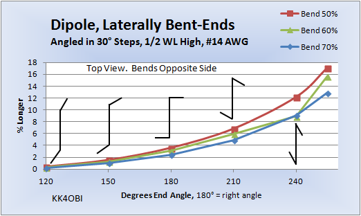
Figure 6
A graphic representation of the angle of bend is shown in black
In Figure 6, compare it with the Same Side data in Figure 4 below. Basically the same but observe that the red line (Bend 50%) and blue line (Bend 70%) traded places. Now, when the horizontal straight section of the antenna is shorter, the % Increase in wire length is greater. Just the opposite of Figure 4.
Figure 4 for comparison
Interesting Tuning Effect, Opposite Sides
In Figure 2 there was a curiosity around the 10% point where the impedance was oddly at 50 Ohms. Optimizing for lowest SWR found that 12% was the best length with the bent arms at right angles. Another way of looking at this effect is that the dipole has been shortened 12%-3% longer = 9% with no perceptable change in gain (7.24 vs. 7.35 dBi) and slightly more radiated power (1.05 vs 1.37 SWR). Also, if we were to bend the arms greater than 180� that would reduce width and shorten the dipole even more because of the overlap. An interesting possibility.
What happens at 12% if we vary the angle of the bent arms?
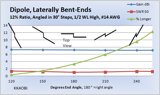
Figure 7
A graphic representation of the angle of bend is shown in black
The answer turns out: "Practically nothing, other than the length of wire gets longer at greater angle."
Gain is flat. It starts at 1.33 dBi at 120� and ends up at 1.25 dBi at 255�... an undetectable 0.08 dBi change.
SWR is almost flat. It starts at 1.33 at 120�, drops to 1.05 at 180� and ends back at 1.25 at 255�.
Conclusion: You are free to bend arms with no significant performance change.
Skew effect at 12%, Opposite Sides
Also, as the bent arms become longer, more of the RF is radiated from them! Skew gradually increases. In this case, only 12% of the wire is radiating broadside to the center. 88% of the wire is radiating RF broadside to the bent arms. In this case the result is that the far field radiation pattern is skewed considerably.
Below is a 3D view looking down where the arms are bent to 240�.
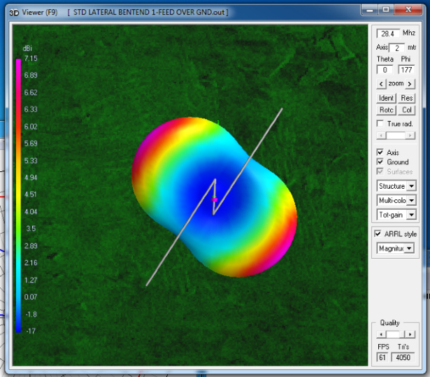
Figure
8
Far Field 3D Radiation Pattern
Far Field 3D Radiation Pattern
The 12% center of the dipole is the segment that appears vertical in Figure 8.. Note that the radiation pattern is skewed almost perpendicularly to the side arms. It basically becomes a "Z" dipole.
SWR is 1.27. Gain is 7.15 dBi. This can be improved.
Optimization gives: A shorter vertical segment 9.13% and bent ends at 216� yielding a SWR of 1.01 and gain of 7.26 dBi with 5.7% longer wire. This is a net reduction in dipole length of around 13.5-14%.
The down-side of this antenna is the difficulty in devising a way of mounting a dipole with a Z at the center. The dipole arms are parallel to the ground and held apart at the feed point by 7 to 12% of the resonant wire length. The "Z" angle needs to be adjustable for tuning. Wind loading will be a problem.
Dick Reid, KK4OBI at QSL.net