
I needed an HF dummy load for my QRP hardware experiments. Had a bunch of 100 ohm 1/2 watt resistors on hand, so used them. 3 in series is 300 ohm, 6 such sets in parallel is 50 ohms, and nominally 9 watts. I wouldn't expect this setup to absorb 9 watts for very long, unless the lid is open and a fan is blowing on the innards. But should be fine for short tests with 2-4 watts. Besides the basic dummy load I added a crude LED power level indicator and a DC output for more accurate measurement of power (or connection to a scope to observe the modulation envelope shape). Here is the schematic:
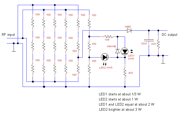
The schematic hints at the construction method where "hot" RF and ground bus wires were run down both sides of the box, and the triplets of resistors alternated connections to either bus. The idea is for the induced magnetic field created by the RF current through each set of resistors to be opposite to that created by its neighbors, so hopefully they mostly cancel out.
The LED circuit is designed so that the first LED starts emitting visible light at about 1/3 of a watt RF input. The second LED starts at about 1 watt, at which point it is far less bright than the first LED. At 2 watts the two LEDs have the same brightness, and the second LED is noticably brighter than the first one when approaching 4 watts. At least that's the theory, I tested it with DC but not yet with RF. The LEDs are assumed to be small "high intensity" (visible light with 1/2 mA current) red-colored LEDs (operating voltage about 1.8V).
The LEDs only light up when the "hot" side of the RF is positive relative to ground, and are reverse-biased on the negative swings. The extra diode across LED1, a small-signal silicon type such as 1N914 or 1N4184, is to protect LED1 from excessive reverse voltage at high power.
The rectifier is fed off a different trio of load resistors since the voltages on the last one are distorted by the LED circuit. Used 2/3 of the RF voltage rather than the full amount because some small diodes are only rated about 40V, and the peak reverse voltage seen by the diode is double the RF peak, since the capacitor remembers the positive peak while the RF is swinging to its negative peak. The diode should be a type that has a low forward-conductance voltage, to minimize the measurement error at low RF input levels. The 1N60 type is described in various web sources as either a germanium diode or a Schottky pin diode, that's puzzling, but either would do. I actually used a 1N100 germanium diode I had on hand.
To convert the measured DC voltage to RF wattage, need to add the diode voltage drop (say 0.2V) to the measured value, add 50% to get the peak voltage at the RF input jack, divide by the square root of 2 to get the RMS value, square that, and divide by the 50 ohms. That is equivalent to this shortcut formula:
watts = (volts + 0.2) ^ 2 / 44.44
For example, a measured 8 volts DC translates to 8.2 * 8.2 / 44.44 = 1.51 watts.
The DC output can also be sent to an oscilloscope (with DC input capability) for observation of the RF envelope shape. The capacitor and resistor are chosen for a time constant of about 1/3 of a millisecond, to allow observation of the envelope shape changes using two-tone audio signals, or PSK31.
I used an RCA connector for the input since I had it - and a BNC-RCA adapter - on hand, and it's cheaper than a BNC or UHF jack. For the DC output I used a 2.5mm mono phone jack, to make it different from the RF input. Here is an image of the completed unit:
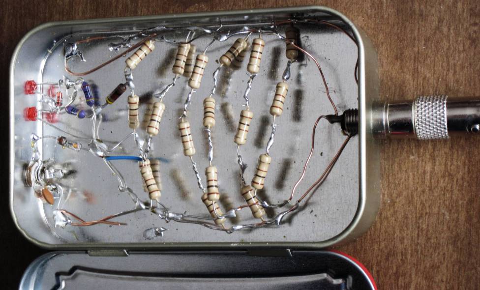
After taking the photo, I adjusted the 3-dimensional wiring to avoid any shorts, and also added insulating tape over the "hot" side buses on both sides.
This is my first project built inside an "Altoids" tin. I found out that it is easy to solder to the inside of the tin, which is a quite useful property. It is made of steel, I presume, since magnets stick to it. But must be coated with tin or something. See solder points in the photo, in the upper left and lower left corners, connecting the ground bus wires to the tin. Another one like that is hidden right under the RF input connector. I've been looking for a source of solderable sheet metal. Heard that "Heinz Beanz" cans are useful that way, but havn't found any around here. If you know of other solderable tins, let me know. Email me at my call sign on qsl.net.