QRC-222
- COVERT RADIO
SECOND SECTION LEFT - Transceiver and transmatch
The second section holds the H.F. Transceiver
and beneth it a transmatch
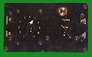
LEFT TOP - The transceiver unit
is unique it has no nomenclature plate or serial number just a dymo
label tape to give a clue to its origins. It does have paper a label
giving an inspection date of 27 Aug. 1965
 Top Panel --
(From top to bottom
- left to right.)
Audio gain, RF gain
Tuning indicator -The frequency range is 2MHz - 20
MHz in 4 bands
1) 2.0 - 3.5 MHz 2) 3.5 - 6.0 MHz 3) 6.0 - 11.0
MHz 4) 11.0 - 20.0 MHz
Calibration adjust knob - mechanical moves the indicator
line back and forth.
5 position mode switch CW, XTAL AM, CW, VFO AM,CAL
Xtal freq adjust, Receive Xtal socket, Receive
Tuning knob
Dimmer pot - to dim the lamp (while peaking the transmitter
power output) - this is a crude form of power meter.
Incandescent lamp - Illumination controlled by above
pot.
Front Panel -- (From top to
bottom - left to right.)
Socket for transmitter coil/crystal plug-in module
Socket for morse key or burst encoder
Power input socket
4 push to insert connectors - push buttons are on
the right side of the unit.
Top to bottom -- 1) Antenna 2) Ground 3) Ground 4)
Phone
Right side -- (From top to bottom
- left to right.)
The 4 push buttons stated above
3 position rotory switch - Receive, off, Transmit
4 position rotory switch - frequency plan same as
tuning indicator above.
Top Panel --
(From top to bottom
- left to right.)
Audio gain, RF gain
Tuning indicator -The frequency range is 2MHz - 20
MHz in 4 bands
1) 2.0 - 3.5 MHz 2) 3.5 - 6.0 MHz 3) 6.0 - 11.0
MHz 4) 11.0 - 20.0 MHz
Calibration adjust knob - mechanical moves the indicator
line back and forth.
5 position mode switch CW, XTAL AM, CW, VFO AM,CAL
Xtal freq adjust, Receive Xtal socket, Receive
Tuning knob
Dimmer pot - to dim the lamp (while peaking the transmitter
power output) - this is a crude form of power meter.
Incandescent lamp - Illumination controlled by above
pot.
Front Panel -- (From top to
bottom - left to right.)
Socket for transmitter coil/crystal plug-in module
Socket for morse key or burst encoder
Power input socket
4 push to insert connectors - push buttons are on
the right side of the unit.
Top to bottom -- 1) Antenna 2) Ground 3) Ground 4)
Phone
Right side -- (From top to bottom
- left to right.)
The 4 push buttons stated above
3 position rotory switch - Receive, off, Transmit
4 position rotory switch - frequency plan same as
tuning indicator above.
 LEFT BOTTOM - TRANSMATCH
A simple low power 11 tap inductor/variable cap transmatch
with tuning lamp.
<PREVIOUS ----- <HOME>
----- NEXT>