BUILDING A 1929 STYLE TNT TRANSMITTER
Late last fall I saw an announcement regarding the upcoming '1929 QSO Party' (more properly known as the 'Bruce Kelley Memorial CW QSO Party') sponsored by the Antique Wireless Association (AWA). Transmitters used during the event must only utilize 1929 or earlier designs, including the use of tubes only available in 1929 or before! Crystal controlled oscillators are not allowed and all transmitters have to utilize self-excited oscillators! Listening-in on the event was truly a glimpse back in time...a much simpler time when the roots of radio were just starting to grow. I could only imagine how different the bands must have sounded back in the late 20's when virtually all signals chirped, shifted, swayed in the wind and were anything but T9! Surprisingly many of the signals I heard sounded wonderful, considering the simplicity of the transmitters being used. I was pretty much convinced from that moment on that I wanted to be part of next-year's event. The final push came after watching and listening to WØVLZ's (Neil) superb YouTube videos demonstrating his own 1929 transmitter and another showing N2UOV (Joe) and his beautiful little TNT. I defy anyone to watch these without wanting to roll-up their sleeves and start building immediately!
After some research into the 1929 transmitter style, it became apparent that most amateurs of the period were using either a Tuned-Plate-Tuned-Grid (TPTG), a Hartley oscillator or a Tuned-Not-Tuned (TNT) design. I can well imagine the countless late night 160m AM QSO's of the day discussing and arguing the virtues of each amateur's chosen design. Eventually I decided on the TNT, a simpler off-shoot of the TPTG design.
The TNT uses an 'untuned' grid circuit, relying on the inherent tube capacitance along with distributed coil capacitance to achieve the slight off-resonance grid tuning needed to sustain oscillation (more on this later)....besides that, it looked simple enough for a 'first effort' and might just get me into the contest! Fortunately my radio library contained a 1931 Radio Amateurs Handbook that provided all of the information needed to construct the transmitter.
Gathering or manufacturing the needed parts turned out to be less difficult than expected. A 'wanted' posting for the brown ceramic 'beehive' insulators brought a friendly response from dedicated '29-style' builder, Lou, VE3AWA. Lou was very interested in working the west coast during the upcoming QSO party and was willing to send me the needed insulators with only one proviso -- I must not only build the transmitter but also use it on-the-air to regularly activate the rare 'west coast'. I assured Lou that indeed I would do just that. Once the insulators arrived, along with a few other goodies, construction began.
The Art of Winding 1/4" Copper Coils
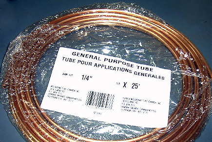
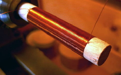
The first job I tackled was winding the 1/4" copper tubing plate coil which I found readily available in twenty-five foot rolls at my local hardware outlet. Some builders have reported that their copper tubing was too thin and would collapse when rolled onto the form. The tubing that I found had a wall thickness of 1.2mm and seemed easily workable. It was hard enough to easily roll into a coil and still maintain its shape without any sign of collapse.
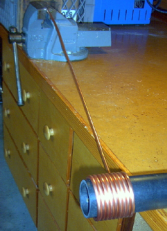
I found that the easiest way to wind the coil was to calculate and cut the length needed then stretch it out with one end clamped in a vise. The other end should be flattened in a vise, drilled and then bolted to the winding form. Fortunately the coil diameter of 2 3/8" was also the same diameter as modern-day ABS tubing which made the task fairly easy.
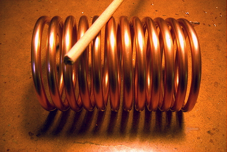
Early Handbooks also have a nice section devoted to the art of winding 1/4" copper coils. Once the proper number of turns is reached it is just a matter of flattening and drilling the other end and then spreading the turns apart with a small dowel. I initially wound the 80m plate coil and the antenna coil. Once I had the circuit working well enough on 80m, I wound a plate coil for 40m as well. I haven't been brave enough to try the TNT on 20m yet but I will eventually wind a set of coils to see how it sounds!
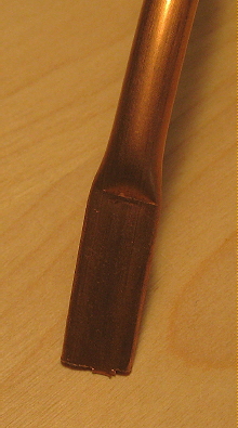
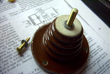
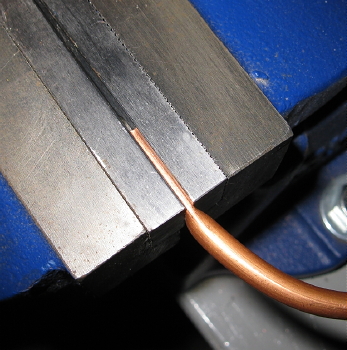
These two images (courtesy of VE3AWA ) show the best method of flattening the copper coil ends. Using a vise with reversible (smooth) jaws and squeezing the copper as tightly as possible will result in a very flat unmarked surface. Lightly center-punch the location of the required hole and drill at a low speed, with the flat end supported on a block of wood. Start with a small hole, gradually working up to the required size before cleaning up the flattened ends with a file.
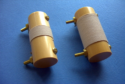
Next on the list were the grid coils. Back in the 20's these were either wound on bakelite tubing or on well-sealed wood dowel. Not having any bakelite made the choice any easy one. The 1" forms were made from some Yellow Cedar that I had gathered from the local beach.
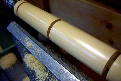
The forms were sealed with several coats of polyurethane varnish before winding the coils and mounting the associated hardware. A more 'traditional' method from the era is to seal the wooden forms with paraffin before winding the coils. This is done by simmering the paraffin at the lowest possible temperature (do not boil!) and allowing the immersed dowel to soak until the air and water have stopped bubbling out of the ends.
While I had the lathe going I also turned a form for the RF choke and wound it by slowly rotating the headstock by hand. The choke turned out to work very well on both 80 and 40m.
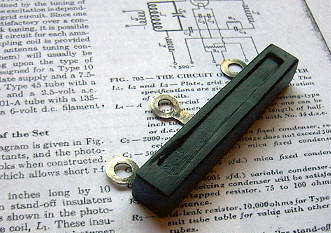
The center-tapped filament resistor was fabricated to resemble the original bakelite-enclosed 'Pilot' style, popular in the late 20's.The pictures indicate how this was done and the finished result. The small plexi-glass form was filled with black Fimo baking clay. After allowing the dough to dry for a few hours, the form was removed and the entire package was baked in the kitchen toaster oven at its lowest temperature for several hours. This achieved the desired hardening effect and a suitable reproduction Pilot filament resistor.
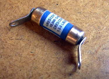
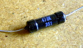
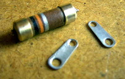
The grid leak resistor was a reproduction also, of an early 'Lavite' model. The ends of a new wire-wound resistor were removed and found to be made from brass. These ends were then fitted to the body of an older style 10K resistor, soldered, painted and labeled with a small 'Lavite' label. The grid leak is fastened directly across the terminals of the grid cap. I found out later that the actual value of the grid leak is quite critical in the TNT. I tried various values and luckily the one I had manufactured turned out to be perfect. My earlier breadboard mock-up model, using a Type '45 (UX-245) instead of a Type '10 (UX-210) required a far larger grid leak to produce best keying and good output. If you are making your own grid leak I would recommend that the value be optimized first, before the grid leak is built in its final form.
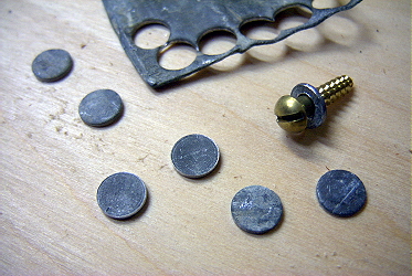
Along with the precious ceramic 'beehive' standoff insulators, Lou also sent me a small piece of lead sheet in order to make some lead washers. These were particularly important if I was to avoid a heart-sinking 'cracking' sound while fastening them to the breadboard. It is also important to place washers on the main (coil mounting) screw both inside and on top of the insulator before tightening the coils in place. I used a small hand-punch to make the discs and then drilled out the holes on a drill press. Thankfully I heard no cracking sounds!
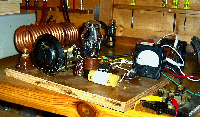
Once the needed parts were made, the circuit was breadboarded - first using the Type '45 and later with the Type '10. Various values were tried for both the grid leak and for the grid capacitor. Both affect keying and output so it is well worth the time spent at this stage optimizing your particular configuration. I also changed over to shunt-feeding of the plate voltage in order to remove high voltage from the large exposed tank coil. I did not want to run the chance of accidently grabbing hold of it late some evening while changing bands. Other than removing the plate voltage from the tank coil, I could not detect any other operational difference between shunt-feed and the standard series-feed method. It saddens me to think of all of the amateurs of the 20's or 30's that may have been unnecessarily hurt or killed when accidently or forgetfully contacting the high voltage on their plate coil.
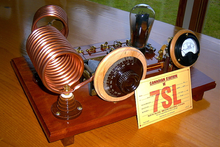
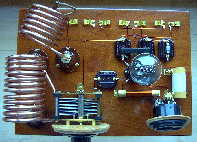
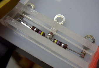
Once the final part-positioning and part values had been determined, the finished version of the '29 TNT was built, tested and put on-the-air for some real two-way work.
One of the first QSO's made was on 80m with Lou, VE3AWA...a most gratifying culmination to several weeks of building. The real test came a few weeks later during the 'AWA's 1929 QSO Party' for 2009. I had been hoping that the calm wind conditions during the days leading up to the contest would continue. Even the slightest amount of wind blowing the antenna will cause these types of 'directly-coupled' power oscillators to change frequency as the antenna impedances drift up and down with the swaying antenna! A mild breeze imparts an 'interesting' note that most '29 operators enjoy hearing as it realistically reflects what many real 1929 signals must have sounded like. Once the wind becomes severe however, the shifting note becomes difficult to tune in. Luckily conditions were excellent and in spite of the very high wind conditions, the little TNT was able to work 36 other '29ers as far east as NY, ME, NH and PA. Hearing some of those great sounds of 'early radio' as well as producing them myself was a night I will never forget.
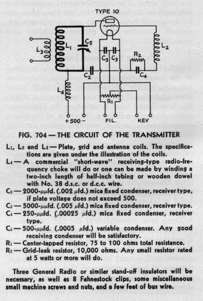
CIRCUIT DIAGRAM & PARTS LIST
GRID CIRCUIT OPTIMIZATION
The original Handbook article describing the TNT indicated that:
"the number of turns on the grid coils may require some modification. Turns should be added or removed until the set operates stably and efficiently over the required frequency band." I soon found out what this really meant in terms of note quality as well as plate efficiency. With the transmitter operating into a 50 ohm dummy load, the frequency control (C5) was set to my intended operating frequency of 3560 kHz. The plate current and power output were noted as well as the keying. The keying was quite chirpy and the frequency would drift down the band the longer I keyed. I then swept the frequency control across its entire range and observed a pronounced dip in plate current at one particular spot which was around 3900 kHz. Although the power output had not changed, the plate current was considerably less, indicating a much better plate efficiency at this frequency. Evidently my grid coil was tuned to 3900 and would need more turns to bring this "sweet spot" down to 3560. The second important observation was that the keying was virtually T9 at 3900 and the keydown drift was now gone since the tube was no longer generating and having to dissipate extra power in the form of heat. Once I had brought the grid coil down to 3560, the much improved operating conditions noted higher in the band were now right where I wanted them. The same effect was noted on 40m as well but in that case, I had to remove turns as the grid coil was initially too low in frequency. If you are building a TNT, optimising the grid coils is well worth the time spent. I suspect that the TPTG design would allow the grid to be very easily tuned to the correct spot and thus much easier to optimize. With the TNT not requiring a second variable capacitor (likely an expensive item back in the depression days), the simplicity of the circuit was certainly its main attraction. In spite of its spartan nature, a properly optimized TNT is capable of very nice performance. Here is an "on-air" recording made of my TNT while transmitting on 7050 kc.
SHUNT-FEED
As noted above, I strongly recommend that all TNT's be changed to a shunt-fed plate in order to remove the high voltage from the exposed plate coil and variable capacitor. It requires no extra parts to make the change as shown below:
ANTENNA COUPLING
In order to efficiently couple a more modern 50 ohm coaxial-fed antenna system, a variable capacitor must be connected in series with the original antenna tank coil as shown below. My own antenna tank circuit required 550pF to resonate on 80m and 310pf on 40m. The more turns on your antenna tank coil, the less variable C will be required.
POWER & PLATE EFFICIENCY
The following values were measured into a 50 ohm load:
'29 - STYLE LINKS
LINKS FOR '29 BUILDERS - Everything you're looking for ... in one place!