About KM Rover
Important: Only the <Enter> and <Space> keys can be used to accept input data and move to the next field. <Tab> is only used to move between fields without using the mouse.
Keyboard shortcuts can be used instead of the mouse.
4 and 6-digit grid data | Log submissions
Auto Load a log file | Manual rotor offset
Band change | Merging files
Bands to be worked | More Band change options
Band Switching | Mouse Usage
Beam Headings | Moving TX Windows
Cabrillo log file | Printing HELP
Club competition | QSO Rate
Current Grid Square | Save window position <<= Use this index - or use <Ctrl + F> to search a topic.
CW option | SQUARES application
Data File Lookup | Start a new contest
Delimited shortcuts | Shortcut cheat sheet
Dupes | Tracking Data
DVK option | Transverter IF Frequencies
File Back-up | TX Mode
GPS Interface | Using the GPS
Grid Squares | UTC time
Load an existing log file | Windows shortcuts
Use this software to log the `big 4` ARRL VHF/UHF contests and Sprints in the Rover category and VHFLOG to log all other categories. Use my GenLog logger for hundreds of HF contests and >55 VHF/UHF contests not supported by VHFLOG.
KM Rover allows QSOs with the same station (and bands) while you move from grid to grid. A limit had to be set, so you can move to a maximum of 50 grids with this logger. This logger keeps track of QSOs with other rovers, allowing you to work the same rover station on multiple bands while that station moves to multiple grid locations. The logger is set for a 2500 QSO limit - this should not be a problem. In addition, the KM Rover allows dupe QSOs to be entered and keeps track of them. Rover callsigns are entered as [call/R]. See Entering Call Signs.
To start a new contest:
Make sure the computer clock / date and the UTC offset are correct. See UTC Time.
Note:
1. Do not enter your call sign with a slash into the setup screen. Using the slash will cause an error when writing files, since it will cause an illegal Windows filename - W3KM/R.log for example. Use W3KM-R or W3KM_R instead. The Cabrillo file will be named {urCall-R.log}.
2. You can use this software as a single-op non-rover. Enter just your callsign in the setup screen and change your category in the setup screen. The Cabrillo file will be named {urCall.log}. Edit the Cabrillo header as needed.
In the setup screen, enter the appropriate information, including your initial Grid Square. If you enter a 6-digit, the beam heading and distance calculations will be more accurate. Of course, 4-digit squares will also work if you don`t know the 6-digit.
Click the [Contest] label or the [Contest name] label or use the File New Contest menu to select a new contest. Then click the [Enter new file] label or use the File New filename to enter a filename. Long filenames are OK in the 32-bit version, but keep them simple so they fit in the display windows.
The log file you named has a Rover Log extension. Example: <2kjune.RLG>
Using this extension keeps the rover logs separate from the Gen Log and VHFLOG files. Entering a filename that tells you what the contest is, will be helpful - ie: 2015june 2015sept etc.
After a contest is started, that contest file can be re-loaded at anytime by clicking the filename in the files listbox. Re-loading a file can be used as a reset. If you are going to merge log files during the contest, move all *.rlg log files to another folder before starting a contest. Then you will be sure that only the log file in the files listbox is the one you are using.
Post contest log entry:
After selecting the contest and entering a log filename, select the {After contest} radio button. The QSO UTC date format is shown. Enter the new UTC date in the same format, then starting at the `Time` field, enter the exchanges from left to right using either <Enter> or <Space>. When the UTC date changes, change it and continue the QSO inputs.
Load or continue from existing log file:
After moving to the next grid for example, click an existing filename from the files box to re-load it. You will be reminded what the last location was and that 6-digits are more accurate. This reminder can be turned off under the Log menu. The files listbox can be updated if necessary by clicking the blue filename box.
At startup, you can Auto Load the log filename used in the last session. Use the Log menu and check the menu item Load last file on startup to activate this feature. If for some reason you deleted the last log use (maybe a test file) and you had the option set to auto load the last log, this results in a 0-byte file being loaded.
The logger will use the 6-digit for calculations but will truncate all entries to 4 digits to be used in the LOG. You can enter a 4 or 6-digit for a station you want to work also. That station`s beam heading and distance can be calculated before the QSO takes place. <Tab> over the grid input field and enter the station`s 4 or 6-digit grid.
You can enter a station`s signal report into your log for QSL purposes if you want. The report field does not show up in the Cabrillo file.
Beam Headings:
The logger uses 4 or 6-digit grid calculations to display the distance and heading to a target grid square. Using a GPS unit interfaced to the logger, the compass heading to a target can also be displayed relative to the front of your vehicle, so you can point the antenna while driving. When driving to the next grid square, the distance and estimated time to the `next` target grid can be displayed. A manual offset can be used if you do not have a GPS connected or when you stop driving.
Control Options/Switches:
Checkboxes and menu checking are used to turn On/Off different options. See Control Options.
Current Grid Location:
If not using the GPS interface, when you move to another grid location, click the current grid square label  and enter your new grid square. As mentioned, you should enter 6-digit grids whenever possible.
Alternately, when you move to another grid square, entering g=fn20jk into the callsign field will change your grid square to FN20jk for example. Not case sensitive. This allows changing your grid without using the mouse. Your current 6-digit location is always displayed in case someone asks. Or, a GPS unit can be used to automatically provide the 6-digit grid square you are in. This is helpful to rovers who are driving during the whole contest.
Club competition:
If you are not submitting your score for a club or the contest does not have club competition, leave the {Club Affil.} field blank in the setup screen. Otherwise, you can always edit that line in the Cabrillo file before E-mailing it to the League.
CW and DVK TX windows:
You can move any of the 3 transmit windows to the desired location using the Windows drag mode. Grab the blue title bar with the mouse and drag the window. It will stay at the new location until you exit the program.
Disable the transceiver`s PTT control.
Hit [Ctrl] to move the keyboard CW TX window.
Hit one of the CW F-keys to move the CW memory TX window.
Hit F12 and move the DVK TX window while in the RX segment of the repeating F12 message.
Exit program:
Exiting KM Rover using the upper right [X] will save the current window position, in case you don`t want it in the middle.
File back-up:
You can select a drive\path where you want your automatic back-up logfile to be saved - even to USB drives.
Files used:
The software uses several ASCII datafiles for callsign lookup. The file [sixdigit.dat] is written by the SQUARES application and contains call signs and 6-digit squares of frequently worked stations in your area. Make a new one, or modify the one I supplied. This 6-digit lookup is an older function - the newer ADIF file lookup can replace this - See ADIF below.
The file [logsort.dat] contains `good calls` and bands the station has, taken from high scoring January SS logs. Bands to be worked data is taken from this file. The file is written by the LOGSORT application using VHFLOG format log files. The [logsort.dat] file that I supplied is from the Pack Rats in the NE part of the U.S. If you don`t live in Pack Rat country, you should make a new file, or delete the one that I supplied. Select the {Bands} checkbox to search the the file each time you enter a call.
Also, 2 other files are used like VHFLOG for callsign lookup. The local club datafile [cklist.dat] and frequently worked stations datafile [ck2list.dat] are used to display the operator`s name. You can make these for any local club or local area.
You can modify the [ck2list.dat] datafile that comes with the logger or write your own using NOTEPAD. The format per line is: Column1: callsign<Spaces>Column8: Name
ADIF lookup file: In the File menu, select the use of the master ADIF file lookup. Select the ADIF file to be used. The callsign will be searched in a master ADIF datafile (like vhf4k.adi originally written by Pete, K9PW, edited/updated by W3KM). If you wish, you can use mine. Select using this file or select the HISTORY file described below.
During the contest, use the File View/Edit ADIF menu to view the file or edit/add 6-digit grids. Re-save the file to use the updated data. To change a 4-digit to a 6-digit grid, edit the # of characters ID to 6 and edit the grid to 6-digits. ex: <GRIDSQUARE:4>FN31 changes to <GRIDSQUARE:6>FN31pq. All other formatting is not disturbed.
GPS interface:
Connect your laptop to a GPS unit and view specific GPS data while mobile to a rover location. Data includes course heading, elevation, 6-digit grid square, number of satellites and longitude/latitude. Compass heading and distances to target grids are displayed while driving. Tracking data can be automatically saved for post contest route and schedule analysis.
History lookup file: In the File menu, select the use of the HISTORY file lookup. The callsign will be searched in the text file and the Op`s name, bands used and 6-digit are pulled from the file. Select using this file or select the ADIF file described above.
Mode:
Change the mode if you wish. Since the mode is not required as part of the exchange and QSOs can be cross-mode on UHF/microwave, the mode can remain as PH throughout the contest. To keep your log as accurate as possible, you can change the SHF microwave and Laser contacts to CW. Use PH for SSB contacts since the Cabrillo file only has a 2-character mode field. Enter [CW] for CW and [PH] for phone.
Open/View files:
KM Rover writes several files that you need to view, verify and possibly edit, before sending them to the contest sponsor. Copy either NOTEPAD or EDITPAD.exe to your logging folder to have the logger open the file automatically after writing it.
Q-Rate:
After working more than 10 QSOs, the QSO rate will be displayed right below the band label. Since the rate is only calculated using the whole minute times for the last 10 QSOs, the displayed rate is a rounded-off number. Note: When the UTC time changes to the 00 hour, the rate will be zero (or blank) until enough QSOs are worked to make a meaningful calculation.
Resizing forms:
A third-party resizing control allows full screen operation by resizing all controls, labels and text (except pull-down menus). You may set the size of most forms - Edit screen, CW setup, DVK setup etc). The size/position settings are saved when you close the form, usually with upper-right-X. All grid maps are opened in the Maximized mode.
Typing while in CW or DVK TX:
The main window logging functions and mouse buttons are disabled during CW and DVK transmit. Windows takes control of the program while it completes playing the DVK wave file. During the DVK transmit, the keyboard buffer will allow you to enter a call sign if you have to. You won`t see the keyed input until the DVK function is completed. This will at least allow you to enter a call before you forget it.
Applications
These support applications are either supplied with this logger or supplied with VHF LOG.
LO is an App used before transceivers that have transverter frequency readout. It is used to setup the displayed I.F. frequencies on each band while logging. Transverter local oscillator and PLL offsets as well as indicated dial frequencies are entered into this application. Can be run from the Options menu. Datafiles written are [xtalx.dat] and [beacon.dat].
LOGSORT can be used to compile your own `good calls` data file from previous contest logs. The data file used by the logger is [ logsort.dat ]. If you select to use the HISTORY file option in the File menu, the {VHF-History.txt} file will be search instead. The Op`s name, bands used and 6-digit are pulled from the HISTORY file.
SQUARES is a grid square calculator. Use it to save a 6-digit datafile [sixdigit.dat] of frequently worked stations, used by the logger. Can be run from the Options menu. The use of the [sixdigit.dat] file is old now. Either use the [vhf4k.adi] file or the {VHF-History.txt} file, both options are selectable in the File menu.
SKEDULER is a multiple alarm that can be used to remind you of schedules throughout the contest period. Up to 20 alarms may be set using the UTC date and time.
UTCTIME can be used to adjust the UTC hour in your log file. If you had the UTC offset set wrong, you can fix your log file post contest. UTCTIME allows you to change the QSO times by X hours. Sorry, only the hour can be changed. UTCTIME can also be used as a general LOG viewer. A back-up file named [ logfile.bak ] is written before you make the changes.
Band change
Band change is easy, although it is also easy to forget to change bands in the logger. Get in the habit of changing bands in the logger before changing bands on the radio.
To change bands, enter the band you are changing to, in the `Call Sign` field. Entering the first 2 digits will work for all bands.
examples:
6 or 50 to change to 50-MHz
2, 14 or 144 to change to 144-MHz
22 or 222 to change to 222-MHz
12 or 1.3 or 1296 to change to 1296-MHz
23 or 2.3 or 2304 for 2304-MHz
47 or 47000 or 47G for 47-GHz etc.
LA or LASER selects the Laser band.
Or, select the band from the {Band} box.
Or, click the band in the {Bands needed} window.
Or, PageUp and PageDown to go to the next band - disabled when using USB band switching.
See optional Band Change functions.
The exact transverter IF frequency is displayed when you change bands. See the IF Frequency topic.
Band change, Options
The following band change functions are provided for Rovers who want to log as fast as possible with the fewest keystrokes. Tnx to K5UHF :-)
Use the Options Band Change Shortcuts menu to access these functions. The selected keystrokes are displayed in the upper right menu bar.
Click <Defaults> for default values, which are:
Band change via normal keystrokes and/or mouse click as defined in the previous Band Change page. Don`t recall the last QSO during band changes. And all CW/DVK functions operate normally.
To recall the last QSO callsign and grid with a band change, check { Recall last Q Call }. If you`re not moving a station up the bands at the time or that callsign isn`t the one you want, just hit <Esc>.
Band change with one keystroke, F-Keys:
If CW and the DVK are not being used, click { Use F-Keys } to use the F-Keys. <F1> = 50-MHz, <F2> = 144-MHz, <F3> = 222-MHz etc.
F-Key <F12> is used to increment to the next band. <F11> will decrement to the next lower band.
PageUp to increment to the next band. PageDown to decrement to the next lower band.
Note: These 2 functions are disabled when USB band switching is selected.
Band change with 2 keystrokes, maintaining CW and DVK:
Select [ Use Special function keys ], then select one of the following:
<ALT> + numbers 1 thru 0, equal to the bands 50 to 10368-MHz. <ALT> + letters cannot be used since this is a Windows function that would access the pull-down menus.
<CTRL> + numbers 1 thru 0 equal to the bands 50 to 10368-MHz. Obviously if the <CTRL> key is selected, then only <F8> can be used as the CW PTT control for the keyboard CW.
<CTRL> + letters A to L, plus 9, equal to the bands 50 to Laser.
A = 50-MHz, B = 144, C = 222, D = 432, 9 = 903, E = 1296, F = 2304, G = 3456, H = 5760, I = 10368, J = 24G, K = 47G, L = Laser. The ARRL started using the `9` as the 903 identifier, I guess I`ll use it too. Making a paper template will help.
You can use the [ Recall last Q CallSign ] function with all the functions above.
Band switching
The Band Switching encoder is supported on older PC`s with an LPT port.
Or, on Win7 and Win8 PC`s without an LPT port by using a CanaKit UK1104 USB to LPT adapter.
If interested in this, read the VHFLOG Help on Band Switching.
Cabrillo file
To send the file to the ARRL:
A new method recently required is the on-line upload for ARRL contests: http://contest-log-submission.arrl.org. Read more in the Nov 2016 QST page 82. Fix any submission errors or requirements and re-submit.
The file must be checked and possibly edited before you E-mail it. Check the rules for submissions for the contest in question.
Important Note:
Each time you select {Log} {Write Cabrillo Log}, KMRover writes over the existing Cabrillo log file in your KMRover folder. Don`t rename a contest log file or copy a file to {urCall.log} - as it will be overwritten by the Cabrillo file and your log will be gone forever. I have been using the .log file extension in my software since 1983 and I don`t want to change it and all of my support applications.
Do not enter your call sign with a slash into the setup screen. Using the slash will cause an error when writing files, since it will cause an illegal filename (W3KM/R.LOG). Example: Post contest change your callsign in the header to `urCall/R` and use the `find & replace` function of an editor to change the rest of the Cabrillo file. Find `urCall and 2 spaces` and replace with `urCall/R`. This will maintain the columns in the file. Lastly, you can edit the Cabrillo filename to be `urCall-R.log` before submitting it to the sponsor.
Unlike other electronic LOG files, the Cabrillo file does not contain QSO points, nor indication of when multipliers were worked. Using the Cabrillo file, the log checkers figure out the points/QSO, add up the multipliers and cross check logs for accuracy using software written for just that purpose.
Copy NOTEPAD.exe or EDITPAD.exe to your logging folder to have KMRover open the file automatically after writing it.
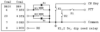
COM ports for CW/PTT
The upper portion on the Communication Settings form is for real COM ports. The third-party DLPORTIO driver is required for this setup.
CW and PTT are keyed thru the RTS and DTR connections of the COM Port. You can reverse DTR and RTS in this setup screen when required.
Using USB CW/PTT interfaces or USB to Serial adapters:
In the lower portion, select the `USB Virtual COM` port option and enter the COM port for the USB adapter.
Obviously a different COM port and setup is used for a GPS connection and is accessed in the GPS form by turning ON the GPS function and hitting the `GPS Setup` button.
You can change the USB adapter`s COM port selection in the PC`s Device Manager.
Start | Settings | Control Panel | System | Hardware | Device Manager
Double-click Ports (Com & LPT). Select the USB Serial Port. Right mouse, Properties. Port settings | Advanced.
Contests supported
ARRL January VHF SS
ARRL June QSO Party
ARRL 222 MHz and up Distance Contest
ARRL September QSO Party
Fall Sprints
Generic Sprints
Spring Sprints
Sprint Contests:
The various supported Sprint Contests change sponsors and rules frequently. Some of them score 1 point for each kM distance between the QSO 6-digits. Some use 1 point per QSO, as they all did back in the day. Multipliers are another issue. Try the Sprint in question before the day of the contest to see if it logs based on the current rules. If not, try another (Spring, Fall, Generic etc). If using a different contest, edit the Cabrillo header to follow the rules; Contest name, category etc.
If you edit the points post contest and edit the summary header and score summary, you can also log other contests.
Control Options
[Bands] checkbox:
Click the [Bands] checkbox to display the bands that a station has in the needed window, after entering that call. The data comes from the file [LOGSORT.dat], which is a written by LOGSORT.exe that comes with W3KM`s VHF LOG software. I update this `good calls` data file periodically and just before each January SS and is available at: http://www.qsl.net/w3km/#kmrover. If you live in the NE part of the US, you can use my file, or make your own.
[Beam Heading / Driving Direction] checkbox:
Display the beam heading to a 6-digit target or display the driving direction that comes from GPS data.
[CW] checkbox:
Activates the CW functions and menu. When not using a CW interface, the F-keys can be used for other functions. Keyboard shortcut [C] and [CO] toggle the CW On/Off.
[DVK] checkbox:
Activates the Digital Voice keyer functions and menu. Use keyboard shortcut [D] and [DO] toggle the DVK On/Off.
[End / Begin] checkbox:
Select END to see the QSOs at the end of the log. See [L1] [L2] [L3] & [L4] shortcuts
Select BEGIN to see the QSOs starting at the beginning of the log.
[Manual offset] checkbox:
Use a manual offset to calibrate your rotor setup when parked - or when not using a GPS. Keyboard shortcut [MO] toggles this function On/Off. `MO` is displayed in the upper right menu bar when the Manual Offset function is ON.

[Printer] checkbox:
Activates the Printer functions and menu. This prevents PC hang-ups when you select a printer function when one is not connected.
[Real Time] [After contest] option boxes:
Real time is automatically selected at the start of a contest and after loading a file. If you want to enter QSOs from a paper log post contest, select the [After contest] option. When you click [After], the date of the last QSO is displayed in the date box.
[Tracking] checkbox - in the tracking form.
When enabled, tracking data is saved to a comma delimited text file, for post contest analysis. Use the keyboard shortcut [TO] to toggle this function On/Off. `TO5` is displayed in the upper right menu bar when the tracking function is ON and shows the 5 minute interval.
CW <F1> setup
The <F1> key can be configured to:
1. Send a normal <F1> message.
2. Call the station entered in the call sign input field, followed by a keyboard message. Select the F1 Call+KB/Norm switch, then enter the keyword <CALL> into the <F1> message to send that station`s call followed by a keyboard CW sequence. After hitting <F1>, the message will be sent as soon as you begin typing your message. You can type ahead and hit <Enter> when finished. <Ctrl> and <F8> also apply to cancel messages.
<F1> Example: <CALL>
3. Call the station entered in the call sign input field, followed by a predefined message.
Select Call+Normal switch, then enter <CALL> where you want it in the <F1> message, followed by the message to be sent.
<F1> Example: <CALL> DE W3KM FN20 FN20 BK
4. Use the keywords <GRID> and <2GRID> in place of your current grid square. When you move to another grid square, you don`t need to change the CW message for <F1>. Even though you enter a 6-digit into your current grid field for heading calculation accuracy, only 4-digits are used for the <GRID>. To send your current grid 2 times, enter the keyword <2GRID>.
<F1> Example: <CALL> DE W3KM <2GRID> BK
Unfortunately, entering <CALL> <CALL> does not send the callsign twice. I didn`t spend much time programming these memories - they are simple and very specific.
If you don`t want to send a call, don`t enter one in the Call Sign input field. If no call is entered in the logging input field, none will be sent even if the <CALL> keyword is used.
CW <F7> mode
The <F7> key can be configured to:
1. Send a normal <F7> message.
2. Key a beacon transmitter or your rig in the beacon mode. A selectable delayed keydown is available.
Or put that old MFJ keyer to work as a beacon keyer.
CW calibration
Since the processing speed of each computer is different, on initial set-up, the speed calibration must be run before using CW. After running the cal, while listening to your transceiver`s sidetone/monitor, adjust the weight setting for best sounding CW at the speed you are using. While the weight range is 0.85-1.25, best keying usually occurs around 1.05 - 1.15, depending on the transceiver. Only small changes are required. Click the [Def] button for the default value.
Save a configuration file for each contest. When you save a file, the current calibration values will also be saved.
CW Interface
A USB to serial adapter can be used for CW/PTT.
Basic Interface
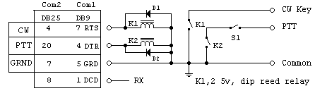
Optional switching circuits:
COM port: 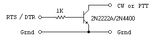
Another interface:
CW Option
COM port setup screen.
Click the [CW] option box to enable CW. Messages are sent with the F-keys, defined in the CW setup. <Space>, <Enter> or <Esc> are used to stop sending.
When using the <F5> message, a selectable delay is used between each repeating transmission.
<F7> can be configured to run in the beacon mode, with a selectable keydown time between IDs. Or, modify your old MFJ keyer to program a key-down sequence and use it as a beacon IDer.
Note: You must run the CW calibration and save the set-up into a configuration file on initial setup. When saving another config file, the current calibration will also be saved. A Speed Constant was added so the range could be set on PCs with precessors >1GHz. Try the default value first.
Use <Ctrl> or <F8> to go to keyboard CW.
CW and PTT are keyed thru the RTS and DTR COM port connections. You can select a software switch to reverse these connections in the COM port setup screen if needed.
A simple interface:
Another way to do it:
Special characters:
In the CW memory messages and keyboard CW, you can send combined characters like AR, BT, SK. Any 2 characters to be sent as one character are entered into the memory message or keyed in as /AR, /SK etc.
CW Speed Control
The CW TX speed can be set as follows:
1. Change in CW Set-up, saved to a config file.
2. While in the Transmit mode, use the up/down arrows.
3. Enter [S##] into the callsign field - to set ## wpm.
4. Hit <Ctrl> or <F8>, use the up/down arrows.
Burst Speed CW
This option comes from my HF logger GenLog, where this is more useful. The CW keyer can be set-up for burst CW. Certain portions of the CW message are sent at burst speed. This speed is set in the CW setup. Any characters contained within parenthesis are sent at the burst speed.
(BK) or (TEST) for examples.
Delete Last QSO
Enter [DL] to delete the last QSO in the LOG. A file named <filename.BU1> will be written before changes are made. In case you want to use this file, rename it to <filename.RLG>.
Before saving a QSO to the disk file, make sure it is correct. It is much easier to delete a QSO right away, rather than trying to edit the file later!
Deleting Files
As with any applications software, it is best to delete files from within the file manager, Microsoft Explorer. The deleted files can be restored if necessary. You may delete 0-byte files. Files with {.bu1} extensions and {.bak} extension files can be deleted when you are finished with them.
Start | Programs | Windows Explorer. View | Folder Options | View Tab. Uncheck the `Hide file extensions` box. Click Apply and OK. This will allow you to view filenames and their extension. Now find the KM Rover folder and delete the file(s). These files (and others deleted within Explorer) can be restored by going to the Recycle bin, clicking the file and doing either the Undo or the Restore function.
Old CW configuration files with the {.cnf} extension can be deleted also. The new file extension for the CW keyer is {.kyr). When you ran the new version of the logger, you probably noticed that a message box came up telling you the files were being renamed. Since 1983 I used {.cnf} as my config file extension, now {.cnf} is Microsoft`s speed dial filename extension.
DVK <F12> setup
The <F12> key can be configured to:
1. Send the normal saved wave message for <F12>.
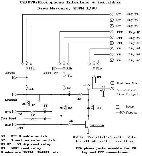
2. The <F12> message is repeatable after a specified delay time. While in TX or delay modes, the repeating function is cancelled by hitting the <Space bar>. The message continues to the end. Use a PTT disable switch (S1 in schematics) to stop the transmission if required.
In the RIGblaster mode, a DVK playing message and <F12> repeating message can be cancelled at any time using the <Esc> <Space> or <Enter> keys. The PTT disable switch is not needed in the 32-bit logger. Read more about DVK over-ride.
Note:
To use the PTT function during DVK operation, you need to have a Com port selected and the CW option must be turned on (even if you aren`t using it).
DVK <F9> setup
The <F9> key can be configured to:
1. Send the normal saved wave message for <F9>.
2. Call the station entered in the callsign input field. The callsign is sent (using alpha.wav files) followed by the standard <F9> message. Select the [Send Call+] switch in the DVK. Using 36 sound card wave files {a.wav, b.wav, 5.wav, etc.}, KM Rover calls the wave file corresponding to the letter/number in the call. Use the sound card software to record and save the 36 files.
DVK files setup
Record your DVK message wave files using the sound software that comes with your PC. Then using the sound card software, remove all the pauses in each file, to make them as short as possible. The histogram portion of the sound card software will allow you to expand the leading and trailing portions of the file, so you can delete the `dead air` parts of the wave files.
Also use the software to edit the volume of each file. Use the VU meter on a phone patch interface to set the same levels. To generate all the alpha/numeric files, recite the alphabet and numbers, then edit them into individual files.
To make callsigns sent by the DVK sound smoother, you can use prefix files. The {prefix.wav} files are sent followed by the rest of the call using the {alpha.wav} files. Record prefix files as explained above for the area you live in, {k3.wav, wa3.wav}. You can make up to 200 files.
You can make other wave files containing the whole callsign if you wish. The call signs could be members of your local club for example. KM Rover will send the call, followed by the rest of the <F9> message.
Note:
You must write a file that tells the logger what prefix or callsign files you have. In NOTEPAD or a WP, make a text file named [syllabls.ini] and enter the prefixes/callsigns, one to a line.
example file:
K3
W3
WA3
WB3
W3KM
Note:
To use the PTT function during DVK operation, you need to have a Com port selected and the CW option must be turned on (even if you aren`t using it).
DVK Interface
Direct connection
An excellent DVK interface is the RIGblaster unit.
My old interface was a modified Heathkit HD-15
Basically the sound card audio is fed into the line input of the patch unit. The mic audio is taken from one of the outputs. Since the HD-15 has both 600-ohm and Hi-Z outputs, it will work with new radios and older types alike. So far, I have tried this interface on the Kenwood TS-180S, Icom IC-451A, IC-751 and Yaesu FT-221 radios. In order to use the interface with the station mic and logging software, you will want to add some impedance matching to the sound card output and switching of the audio and PTT line. If you don`t mind modifying the HD-15, you can put everything inside the box.
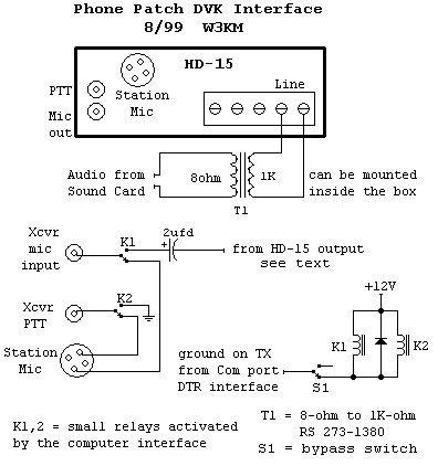
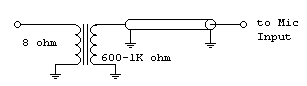
Audio from the sound card (8-ohm) is fed through an impedance matching transformer into the line input (600-ohm). This interface allows the audio level to be monitored on the VU meter and the TX mic gain can be adjusted using the front panel control. The sound card volume can be adjusted to match the station mic level when the `Trans gain` control is mid range. The sensitivity of the VU meter can be increased if necessary by reducing R1 (3600-ohm), which is connected between S1-A to S2-4. The VU meter allows you to set all your wave files to the same level. After recording your files, play each one into the DVK interface and reset the volume of each accordingly.
A small control relay switches the audio between the station mic and the DVK. The newer radios power the mic (8V) from the front panel connector. Unfortunately this power source is current limited to a few mA, so you can`t `steal` the voltage to drive a relay for example. Just the same, don`t forget the 2ufd dc blocking capacitor. Use the 600-ohm audio for new radios and the Hi-Z audio for older radios using a high impedance microphone. Needless to say, shielded audio cables are used for all mic connections. I used one of the RCA phono jacks for the mic output to the radio.
Another small control relay switches the PTT line. The control line from the pc interface (ground on TX) can be connected at the SPKR terminal for example. The wire going to this terminal can be removed. A bypass switch should be wired into this line to act as a PTT bypass, if the wrong F-key is pressed for example (S1 in schematics). Connection to the radio`s PTT line can be made via the other RCA phono jack. I used a single DPDT relay to switch both the audio and the PTT line.
I connected to the 8-ohm speaker output of my sound card since the level of the line output was not high enough to drive the DVK interface. There is more than enough audio available. If you want to add an 8-ohm audio attenuator to make the volume adjustment less sensitive, attach a T-pad at the line terminals going into the 8-ohm/1K-ohm transformer.
10dB T-pad: 2 x 4.3-ohm series resistors and a 5.6-ohm shunt resistor to ground.
20dB T-pad: 2 x 6.8-ohm series resistors and the shunt resistor is 1.5-ohms.
DVK messages
Create DVK messages with your sound card software. Save these .wav files to your KMRover folder. Select [DVK] option box to turn on DVK setup and F-Keys.
In the DVK Setup: click on message filename label, then click the file from the filename dialog box. Click a message label, then click [Test] to try that message. Or double-click a filename to test play that wave file. See more about DVK setup.
Message repeat:
The <F12> message can be selected to repeat after a specified delay. While in TX or delay modes, the repeating function is cancelled by hitting <Esc> or <Space> bar. The message continues to the end. Use a PTT disable switch, S1 in schematics (not needed in the 32-bit version) to stop the transmission if required. If you use a sound card interface with your transceiver in the VOX mode, you can wire the TX disable switch to drop out the interface control relay circuit.
DVK over-ride:
In the new logger there are 2 DVK modes available. I did not remove the original `Normal` DVK play mode since users may want to continue using this mode. In the 'RIGblaster` mode, the playing wave file can be stopped at any time - in several ways.
1. Hitting the <Esc> <Space> or <Enter> key.
2. Hitting another F-key immediately plays the new wave file.
If not using the RIGblaster sound card interface, the <Esc> <Space> and <Enter> keys will still cancel a playing wave file in the `RIGblaster` mode.
Note:
A dummy wave file [ stop.wav ] is used to stop a currently playing wave file when DVK cancel is requested in the RIGblaster mode. The file must be in the kmrover32 folder.
Note:
If you are using DVK PTT (and you will when using the RIGblaster), then you need to have a COM port (or USB) selected and connected. When selecting the DVK, the CW setup initializes the COM port momentarily. If CW PTT is not already ON, the DVK initializer turns it ON.
Note:
If you select {Send Call+} to send the callsign of the working station in your own voice, you need to make the associated letter, number and syllable wave files (and syllabls.ini). In the `Normal` mode, missing wave files show up as a blank space being played.
In the `RIGblaster` mode, missing files cause an error. In order for the logger to hold the DVK PTT line high during the playing duration, the length of the wave file being sent is calculated from information read from the wave file`s header. A non-exising wave file causes a divide by zero error - which can be trapped to display the message dialog box.
Edit LOG file
For the most part, you can edit the LOG file in KM Rover.
To edit the LOG, click the label below the clock. 
Scroll the log or click [Search] to look for a callsign in the log, and [Next Call] to find the next occurance of that call sign in the log.
To add a QSO you forgot, click the QSO line that will follow the added QSO. Then click [Add QSO]. Enter the QSO information from left to right using the <Enter> or <Space> keys, as in normal logging. After entering all the data, click [Accept Add]. Click [Refresh] to view the updated Log Window. Click [Save Changes].
To delete a QSO. Click that QSO line. Then click [Delete QSO]. Click [Refresh]. Click [Save Changes].
To edit the log in `Notepad` or in a word processor, make sure you save a back-up file first. When editing the log, keep the same column format (with spaces between, not TABS). If you move the data in columns, KM Rover will not read in the log correctly. If you think you screwed it up, then exit the editor without saving the file.
Entering Call Signs
Dupes:
KM Rover allows you to include dupe QSOs in the LOG. This insures that the QSO will be counted. Previously, you were never sure which QSO to remove from the log, when a dupe was worked. When a station insists on working you again, just log it with 0 points. It will be in the LOG but not counted in your score. The number of dupes is displayed in the menu label up top Dupes: # . Use the Dupes: # Write dupefile.txt menu to write the file.
Dupe QSOs are permitted in the Cabrillo file and the sponsor will not penalize you for them, so don`t remove them from the log. When the sponsor does cross checking, these QSOs will be in the log.
Rovers:
Rovers are logged as {call/R}. When you enter a rover {call/R} a second time, a dupe box comes up. Hit <Enter> if it is a dupe. Or <Tab> over to {Yes} if you want to count the QSO. If you enter a new grid, the QSO will be logged. Otherwise it will be logged with zero points, just as it would be for a dupe QSO.
Normally duping is done after entering the Callsign. When working other rovers, you may not want the dupe prompt to appear every time. Use the Options menu and select Dupe after Grid, which will initiate the dupe function after the grid is entered. When this is selected and you enter a non-duplicating grid for that call sign, and the message does not appear. Note: Accepting a zero point dupe QSO into the log now works in both duping modes.
You should always log a station`s callsign as the station signs it. Rover QSOs should be logged as {call/R} in your log submission. If you do not log Rovers correctly, some of your QSOs could be identified as dupes. Dupes have zero points value.
Callsign shortcuts:
When moving stations up the bands or quickly working the same tailgaters when moving a station through the bands, use the [L1] [L2] [L3] and [L4] shortcuts. Entering [S] will input the same callsign just entered. Double clicking a QSO line in the LOG window will also <Enter> that call sign.
File back-up
For automatic back-up (append), select the back-up drive in the setup screen. Each QSO will be saved to the selected disk drive. Although the quick select combo box only shows the drive letters, you can enter the drive\path of choice into this box. I:\temp - or J:\hambu for examples.
If you want the backup USB device to have a persistant drive letter:
1. Use the Windows key + X keyboard shortcut to open the Power User menu.
2. Select Disk Management.
3. Right-click the USB drive on the list and select Change Drive Letter and Paths.
4. Click the Change button.
5. Use the drop-down menu and select the drive letter you want to use. Choosing
a letter from M to Z will insure it will not conflict with other devices.
If you try to save BU to the logging folder or enter a drive\path that doesn`t exist, an error message is displayed. If you decide that you want to save to BU after you started logging, use the View Auto BU path: menu. When you continue logging, the back-up file will be updated.
To use the auto back-up log file: It has the same name as the logfile being used and is located in the {Auto BU path:}. First view it to make sure it is what you want, then copy it to the logging folder and re-load it.current.
Manual back-up file:
LOG file back-up can be manually saved using the Log Manually Save BU file menu. This is a different procedure than the Auto BU described above. As with any software, it is probably a good idea to save periodically. The file can be re-named and re-loaded into KM Rover. ex: change .bak to .rlg.
There is no reason why you should ever lose contest LOG data. You can have several files available that contain your QSOs. Make sure you know how to use the back-up file(s) and procedures BEFORE a contest!!
These files are saved in your KM Rover folder:
[file.RLG] is the normal Rover log filename.
[file.BAK] is the manually saved BU file, rename to [file.RLG] to re-load.
[file.RL1] is the logging file saved before editing in KM Rover, rename to [file.RLG] to re-load.
[urCall.LOG] is a manually saved file in the Cabrillo format.
The auto-saved file [file.RLG] is written to the back-up drive you selected in the setup screen.
A manually saved file can also be written to diskette under the Log menu.
If a glitch erases or corrupts your normal LOG file, you should have no problem re-naming a file and reloading it into KM Rover.
If you associate the .RL1 .BAK .RLG and .LOG extensions with NOTEPAD, you can easily view or edit them.
GPS Interface
Connect a serial cable from your laptop to your GPS unit and KM Rover will show your Latitude and Longitude as well as the 6-digit grid square you are in. You will be able to tell when you drive across a boundary into a new 4-digit grid square. Your current 6-digit grid is updated and displayed automatically as you drive, as is the actual beam heading to a target grid square.
The GPS is connected to the laptop via a `real` COM port or a USB virtual COM port when using a USB to serial adapter.
Note: If using both CW and GPS, you must use 2 different ports - configured in 2 different setups.
LPT1 is only used for the band encoder - setup in the Options Band encoder menu.
Request for the GPS interface, beta testing and feedback provided by Ken Simmons, K5UHF. See Using the GPS functions.
Click the [GPS Setup] label to go to the setup screen. The setup screen is useful when initially connecting to the GPS. The data flow will be seen when both the correct GPS interface menu selection and the correct wiring connections are made. In a Garmin unit, Page down the menus to {Interface} and select {NMEA / NMEA} or {None / NMEA}. KM Rover is setup to use the default 4800 baud setting.
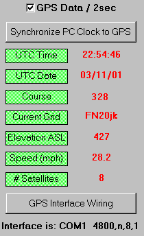
You can synchronize the PC clock to the clock in the GPS system by clicking [Synchronize PC Clock to GPS]. First, make sure the PC hour is set correctly. Then the minutes/seconds will sync. Note: Only the minutes and seconds will sync. Since the GPS sends data every 2 seconds or so, the exact sync time can only be within a few seconds. Note: This function`s button should be disabled when you `Show dummy data`.
Dummy data:
When not using a GPS or when data flow is not present, you may see what the data looks like and see how the direction and beam heading functions work by clicking [Show dummy data].

To make your own cable:
Only two connections are required - ground and GPS data out.
Example connections to a Garmin unit are shown here.
Grid squares
Six-digit grid and 4 digit squares can be entered throughout this software. The calculated beam heading and distance will be more accurate when you use 6-digits. You can enter the stations 6-digit grid before you enter the callsign. This will give you the station`s beam heading to make working the QSO easier.
You can turn off the last `grid square prompt` that is displayed when a log file is loaded. Use the Log Show last grid message menu and uncheck it.
When you move to another site, click the [Current grid square] label and enter your new grid square (if you moved locations and the grid is different).
Alternately, when you move to another grid square, entering g=fn20jk into the callsign field will change your grid square to FN20jk for example. This allows changing your grid without using the mouse.
Also, your current 6-digit grid can be automatically updated and displayed as you drive using the GPS interface.
Simple graphical representations of the US are used to display grids worked. Use the menu to select the East, Mid, West or US map. Select whether to show grids worked on one band or the whole log. Click the [Grid Map] label or enter [G] or [GM] to show the map selected with the mouse. If you want to print the grid map, screen capture it in Paint Shop Pro, for example.
Hint:
A blank grid map screen means the map datafile is missing or empty. KMRover uses these map datafiles:
EastGrid.map
MidGrid.map
NthAmer.map
WestGrid.map
These files are included with the latest upgrade file.
If you hit <Esc> to cancel a QSO, you can use the [LG] shortcut at the callsign input, as well as at the grid input, to retrieve the last grid entered.
Old:
KM Rover uses the grid data file [ sixdigit.dat ] to display the grid for stations that you frequently work. SQUARES is used to make this file and is supplied with the logger.
New:
1. The logger can optionally use the {vhf4k.adi} or similar format file to look up station grid squares. You can manually edit this file during logging.
2. The logger can optionally use the {VHF-History.txt} file to look up Op`s name, bands used and 6-digit grids.
Code used to calculate distances between six digit grid locators was taken from code written by J. Rautio, AJ3K in 1983. This software was available on the ARRL web site.
HELP Manual
Printing the keyboard shortcut sheet is useful.
IF Frequency
If you have one of the newer transceivers that has the transverter frequency display, you can skip the first half of this section.
Throw away your paper notes about dial settings and IF offsets due to transverter local oscillators. Just like VHFLOG, you use the LO.exe application to generate the required datafiles.
KM Rover displays the radio`s dial setting or transverter IF frequencies on each band, due to LO or calibration offsets. When using PLL sources, an accurate VHF frequency counter is used to read the PLL frequency before making a microwave QSO. The Rover logger calculates and displays the IF frequency.
The actual dial reading or IF frequency on each band is displayed for whatever frequency you want to be referenced. The calibration offset is displayed in the [IF frequency] display label located just below the frequency box. 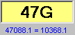
KM Rover calculates an IF frequency.
When a station skeds you on 1296.175 for example: In the call sign input field, enter F175. The IF frequency for 1296.175 will be displayed. If freq <.100, use the format F050, for example. No more calculating the offsets to figure out where you need to set the IF dial. This may seem trivial, but some of us have purposely set our LOs to move the IF far away from normal operating frequencies. My 2304.100 = 28.453 IF.
Beacon dial frequencies.
In the LO application, you can enter your radio`s dial reading for beacons. To display the beacon list, use the Options Beacon Freqs menu, or use the [BC] keyboard shortcut. The beacon datafile is named [beacon.dat].
Example LO datafile:
Displayed or Dial or
Calling Freq I.F. Freq Multiplier PLL (if used)
50.150 50.150 * *
144.200 144.201 * *
432.100 28.099 * *
5760.1 * 60 93.600012
10368.1 * 100 103.681000
24192.1 * 200 103.680000
Phase Lock Sources work !
Do you know where your microwave transverter is?
First, your PLL reference crystal should be temperature compensated for stability. The use of microwave PLL sources is denoted in the LO datafile by the * in the I.F. Freq field. Before working a microwave QSO, read the PLL frequency on an accurate VHF counter (90-110 MHz). Click the [IF frequency] display label  and enter the new PLL frequency.
Notes:
The logger reads the LO datafile sequentially, so an entry must be made in the LO file for each band 50 to the highest one you use (in order). Ignore the excess data.
When using PLLs, the * must be used and the multiplication factor must be entered as shown above.
Depending on the data entered in the datafile, you can display the IF of choice for transverters that have multiple IF`s - like a 24-GHz transverter with a 3456-MHz intermediate IF - driven by a 2-meter rig. To get an accurate IF dial setting for transverters with more than one conversion, you`ll need your calculator - since the logger doesn`t handle this directly.
Make sure you also know the calibration of your IF radio(s).
Key strokes / Shortcuts
When a Button is highlighted,  <Space> or <Enter> will activate that button. This enables you to do logging functions without using the mouse.
Use the <Tab> key to move fields: Call - Grid etc. Don`t expect the <Tab> key to accept the input data, just because some software packages do. The <Tab> key does not accept the data and the duping function may not be done!
Hit <Enter> or <Space Bar> to accept input data. At the last input field, hitting <Enter> or <Space> will save the QSO to file if you have Q Acc(Auto) selected. If you have Q Acc(Man) selected, the [Save above data] button will be activated by hitting <Enter> or <Space> again.
Easy to read, printable shortcuts
<Enter> returns keyboard CW to RX after KB buffer is sent.
The [L1] [L2] [L3] and [L4] shortcuts are useful when moving more than one station through the bands, especially when tailgating stations also move. Last, next to the last, third from the last and 4th from the last in the log respectively. Double clicking a QSO line in the LOG window will also <Enter> that call sign.
Keyboard CW
Use <F8> or <Ctrl> keys to transmit CW from the keyboard. When finished typing/sending, hit <Enter> to go back to the RX mode. Use <F8> <Ctrl> or <Esc> to cancel.
You can type ahead and hit <Enter> as part of the transmitted message. The CW speed can be changed while sending your message - using the `Up` & ` Down` arrow keys.
The PTT feature is also used in the keyboard CW Mode.
Keyboard shortcuts
Read about entering shortcuts without erasing an existing call sign in the call field.
Use F-Keys to send CW or DVK messages.
The <Esc> key clears all QSO inputs.
<Ctrl> or <F8> activates keyboard CW.
Many keystrokes can be used instead of the mouse click.
Shortcuts <Entered> in the call Sign input field:
Enter the frequency to change bands [##]. See band change.
Enter [B], [BH] or [DI] to toggle the Beam Heading/Direction indicator check box.
Enter [BC] to display the beacon frequency listing.
[C] or [CO] to toggle the CW checkbox - On/Off.
[CW] to change to the CW mode.
[DG] to change to the DG (all digital) mode.
[D] or [DO] to toggle the DVK checkbox - On/Off.
[DL] to delete the last QSO. After using [DL], to re-enter the same QSO, enter [L] for last, to retrieve the last callsign entered.
[ED] or [EL] to go to the Edit Log screen.
[F###] to calculate and display the IF frequency for ### KHz.
[FM] to change to the FM mode.
[G] or [GM] to show the currently selected grid map.
[GP] to toggle the use of the GPS interface.
[GW] to show grids worked on current band.
[L] for the last call sign entered. Useful when cancelling a QSO (wrong band), or when deleting the last QSO.
[LG] for the last grid square entered, in case you hit <Esc> want it back. Entering [LG] at the grid input will also retrieve the last grid entered.
[L1] for the last call sign in the log, or bottom line of the log. Same as [S].
[L2] for the next-to-the last call sign in the log, or line 2 from end of log.
[L3] for line 3 from the end of the log.
[L4] for line 4 from the end of the log.
[MF] merge log files.
[MO] to toggle the manual rotor offset checkbox - On/Off.
[NG] to enter the next grid you drive to.
[RL] to run the LO.exe application.
[RS] to run the SQUARES.exe application.
[PH] to change to the Phone mode.
[S] for the same callsign as the QSO just entered, useful when moving a station through the bands.
[S##] changes the CW speed to ##.
[SG] to show grids worked on current band.
[SL] to show the log.
[SS] to show the summary.
Clear/Cancel keys:
<Esc> key clears all QSO inputs.
<Esc> <Space> and <Enter> cancel CW.
Log window refresh
To refresh the Log window, click the [Last QSO label]. The score is also updated. The log is also refreshed after a QSO is entered.
After editing the log in the editor screen, the log window is automatically refreshed when you return back to the logging screen.
Click the [End] box to view QSOs at the `End` of the Log.
Manual rotor offset
When not using a GPS or when not driving with a GPS, you can select and <Enter> a manual offset - to calibrate your rotor setup. Check the [Manual offset] check box (or use the `MO` shortcut). This allows you to park the vehicle in any direction, and still use the beam heading-to-target function. `MO` is displayed in the upper right menu bar when the manual offset is ON.
After station setup, get a beacon or distant station`s beam heading from the upper right corner 6-digit calculator. Peak the antenna on the beacon or station. The manual offset will be the difference between the calculated heading of the target 6-digit and what the rotor control box reads. After entering the offset (a positive or negative integer), the station should peak at the heading given in the heading text display, as well as on the compass.
Note:
Normally your rotor is calibrated to `North` in the direction of your rover vehicle. If your vehicle is parked facing clockwise from North, then your offset is a positive integer. If it is facing counter-clockwise from north, then use a negative number. Check the heading on a station or beacon and fine-tune the offset as necessary.
When using a GPS and are on the road again, you can uncheck the [Manual offset] check box. Or - <Enter> `MO` into the callsign field to toggle the checkbox.
Merging log files
Since the logger doesn`t support networking, merging log files may be required if 2 or more operators are logging on separate bands with separate PCs. This will allow you to create one log file for scoring purposes and for submission to the ARRL. In addition, you may also wish to keep track of stations worked so far by merging logs from different bands during the contest. Merging is limited to files of the same contest. Fortunately, the Cabrillo log submission does not need to be in chronological order
Exporting the file:
Use the Log Save file to diskette or USB menu to save the currently being used log file to a diskette or USB flash drive that can be shared between computers periodically. The keyboard shortcut [SF] will also activate this function. The drive/path used for file export is saved in the ini file for convenience.
Importing the file:
Use the Log Merge 2 log files menu to merge a second file (from different bands, and different filename) with the log file currently being used. The keyboard shortcut [MF] will also activate this function. Navigation is then possible using the <Tab> and arrow keys. The header of log file#2 is parsed before being imported and merged. QSOs in file#2 are compared to QSOs in file#1. Only the non-matching QSOs (QSOs not merged before) are written to the end of file#1. This allows the files to be merged as many times as necessary during the contest. After a file is merged, re-load the file into the logger by clicking the filename in the files box.
You do a merge verification by looking at the last QSOs in the log. They should be the same as the log in the other PC, for example.
Initially the save function defaults to the A:\ diskette drive, but you can save or import files to or from any drive. The drive/path will be saved in the ini file for later use. File export and import can be carried out while in the logging mode without exiting the logger. It is most helpful to have only the current logging file in the KM_ROVER folder while attempting merges. Therefore, move all *.rlg log files to another folder before starting the contest.
Important note:
If you log QSOs on the same bands on the 2 PCs for example, the score will probably be incorrect in the merged file. This is because the logger reads the `# new multipliers` column when figuring out the score.
After merging log files - go to the `Edit/Change log` screen. Select a QSO on the band in question. Click the RX Grid field. Click the `Re-number # new mults` button. The software will re-number the `# new mults` column. Do the same procedure for other bands as required. Save the changes. When you return to the logging screen, both the log and the score will be updated. Write your Cabrillo file.
Another Note:
It is always a good idea to backup your log files to another folder before any kind of manipulation is done. As mentioned in the message box prompt right after a file merge, the current log file is saved with the extension .bak before merging takes place. In Explorer for example, rename the file *.bak to *.rlg and reload to use the previous version.
MFJ beacon IDer
by W3KM, 1995
This modification was done to an MFJ Grand Master keyer, but could be used for other MFJ keyers also. A tune switch was added ahead of the memory circuits so a key-down could be programmed.
The simple mod uses a 330-ohm resistor and a miniature (normally open) push button switch. These components are connected in series between Pin 5 of U4 and ground.
Pin 5:U4 ---- 330-ohm ------ PB switch --- ground.
I soldered the resistor lead directly to the IC pin. The momentary PB switch was mounted on the rear panel.
More shortcuts
Delimiter shortcuts are used to toggle the different functions without using the mouse and still maintain a call sign in the call input field.
A delimiter character is typed between the callsign and the shortcut text. Select either a period, a comma or reverse slash as the delimiting character from the Options Keys menu. These shortcuts can be used with or without a callsign in the call input field. The delimiter character being used is shown in the upper right menu bar.

Examples:
W3KM is in the call input field. Type .G immediately after the call (W3KM.G) and hit <Enter> or <Space>. This will display the currently selected grid map, same as entering `G` does. Or .GP to toggle the GPS interface off/on, same as entering `GP` does. The shortcut is parsed from the entered text, leaving the call sign.
Delimiter shortcuts:
[B] or [BH] toggles the Beam Heading/Direction check box.
[BC] displays the beacon frequency listing.
[C] or [CO] toggles the CW checkbox On/Off.
[CW] changes mode to CW.
[D] or [DO] toggles the DVK checkbox On/Off.
[DG] to change to the DG (all digital) mode.
[DI] toggles the Beam Heading/Direction check box.
[ED] or [EL] for the Edit Log screen.
[FM] to change to the FM mode.
[G] or [GM] shows the grid map.
[G=6digit] inputs you current grid square.
[GP] toggles the use of the GPS interface.
[GW] shows grids worked on current band.
[MF] merge log files.
[MO] toggles manual offset.
[NG] next grid you are driving to.
[NG=6digit] for the next grid you are driving to.
[PH] changes mode to PH.
[SF] save log file.
[SG] shows grids worked on current band.
[SL] shows the log.
[SS] shows the summary.
[TO] toggles tracking On/Off.
Mouse usage
Windows double-click functions are used where applicable.
Moving the mouse during CW TX could cause the CW speed to slow down as Windows completes the mouse move procedure.
To fast exit the program, click the KM Icon.
Double-clicking a QSO line in the log window will <Enter> that callsign.
Note:
The mouse is not needed for normal logging functions. <Esc> <Tab> <Enter> and <Space> are used. <Enter> and <Space> are used to accept input data. <Tab> is only used to move between fields. One or two letter shortcut keys, entered thru the call sign field, are used instead of the mouse.
Push-to-Talk
To use the CW PTT control, click [PTT] in the CW setup. To use the DVK PTT control, click [PTT] in the DVK setup. To use the PTT function during DVK operation, you need to have a Com port (CW) selected.
DTR vs. RTS:
CW is keyed thru the RTS port and PTT is keyed thru DTR of the COM ports. You can select a software switch to reverse these connections in the COM port setup screen.
The PTT option should definitely be used for transverter-amplifier operation. Problems due to sequencing and transients are eliminated by using the hard keying feature rather than semi break-in or VOX.
QSO Accept switch
Select Q Acc [man] to manually click or activate (<Enter> or <Space>) the [Save above data] button.
Or select Q Acc [auto] to automatically save after <Enter> or <Space> on the last logging input. This is useful if you get in the habit of `Entering` the last QSO input ONLY after you get the QSL from the other station.
Shortcut cheat sheet
<Esc> clears all
<Ctrl> or <F8> to TX keyboard CW
[##] to change bands
[B] or [BH] toggles beam heading
[BC] displays the beacon listing
[C] or [CO] toggles CW
[CW] CW mode
[D] or [DO] toggles DVK
[DI] toggles direction indicator
[DL] delete last QSO
[ED] or [EL] edit log
[F###] calculate and display IF freq
FM] FM mode
[G] or [GM] show grid map
[G=6digit] current grid square
[GP] toggles GPS
[GW] show grids worked
[L] last call sign entered
[LG] last grid entered
[L1] last call in the log
[L2] next-to-the last call in log
[L3] 3rd call from end of log
[L4] 4th call from end of log
[MF] merge file
[MO] toggles manual offset
[NG] next grid
[NG=6digit] next grid
[RL] Run LO.exe application
[RS] Run SQUARES.exe application
[PH] PH mode
[RY] RY mode (all digital)
[S] same as last Q callsign
[S##] to change CW speed to ##
[SF] save file
[SG] show grids worked
[SL] show the log
[SS] show the summary
[TO] toggles tracking
PageUp up band
PageDown down band
Clear/Cancel keys:
<Esc> key clears all QSO inputs.
<Esc> <Space> and <Enter> cancel CW.
<Ctrl> or <F8> cancels keyboard CW.
<Enter> returns keyboard CW to RX after KB buffer is sent.
<Esc> <Space> and <Enter> cancel DVK play and <F12> repeat.
Many of these functions are also activated by the mouse. The keystroke shortcuts are for rovers who want minimal mouse interaction.
Six Digit Squares
Note:
The use of the SQUARES datafile for grid lookup is an older function from the `90s. This can be replaced by using one of the 2 new look-up files.
1. The master ADIF lookup function. Select this function in the {File} menu.
2. The master HISTORY text file lookup function. This file has the Op`s name, bands used and 6-digit grid. Select this function in the {File} menu.
Grid data:
For reasons of accuracy, 6-digit grids should be used whenever possible. The logger will use 6-digit data for calculations but will truncate all entries to 4 digits to be used in the LOG. You can enter a 4 or 6-digit for a station you want to work also. That station`s beam heading and distance can be calculated before the QSO takes place. <Tab> over the grid input field and enter the station`s 4 or 6-digit grid. Note that entering an invalid grid square produces a 0 heading value.
6-digit grid squares work !
Removing the antenna `pointing` variable can be quite significant. If you know the 6-digit and your rotor is calibrated properly (to beacon headings), there is little reason for you to search for a station with your antenna. You might need to tweak a dish or big array when you do hear him. Forget the compass, forget magnetic north and forget paper notes. With your antenna on the other station, if you don`t hear him, you don`t have a clear shot or propagation, or you`re not on the right frequency. Using even one 4-digit grid in the look-up or calculation can produce heading results in the opposite direction, since 4-digits headings and distances are to/from the center of the 4-digit.
6-digit grid squares are used by operators to assist in aligning their antennas. If you align your antenna rotor against a beacon transmitter`s six digit, you can put your antenna on the station to be worked and it will be on him every time. After I set the rotor to the station`s heading, I generally don`t move the antenna while finding his frequency.
The beam heading alone can be helpful. When a station is heard or heard being worked by someone else, you will know where to point your antenna.
Sprint Contests
The various supported Sprint Contests change sponsors and rules frequently. Some of them score 1 point for each kM distance between the QSO 6-digits. Some use 1 point per QSO, as they all did back in the day. Multipliers are another issue. Try the Sprint in question before the day of the contest to see if it logs based on the current rules. If not, try another (Spring, Fall, Generic etc.) If using a different contest, edit the Cabrillo header to follow the rules; Contest name, category etc.
Submitting a log file
More about the Cabrillo file.
To send the file to the ARRL:
A new method recently required is the on-line upload for ARRL contests: http://contest-log-submission.arrl.org. Read more in the Nov 2016 QST page 82. Fix any submission errors or requirements and re-submit.
Write the file using the Log Write Cabrillo Log menu. In v4.5 and later, a query pop-up will ask if you want to write only 4-digit grids to the Cabrillo. 4-digit grids are required by the new on-line submissions server. The file name is {urCall.log}. Check the file to make sure it contains everything that the rules require. If you are submitting your score for club competition, make sure it says so in the Club: section of the Cabrillo file. If this contest doesn`t have club competition, make the Club: line blank.
Note: Each time you select {Log} {Write Cabrillo Log}, KMRover overwrites any existing file with the name {urCall.log} in the KMRover folder.
If you copy NOTEPAD or EDITPAD into your logging folder, KMRover will open the log file after you write it.You can also view/edit the file using Microsoft`s File Explorer. The file was saved in your KMRover folder. When you double-click the file, if you don`t have the *.log files associated with anything, a window will open asking what application to use to open the file. Select NOTEPAD from your WINDOWS folder. Edit the file and re-save it, if you made changes.
The following is how to send the Cabrillo file to the contest sponsor.
Notes:
1. Do not enter your call sign with a slash into the setup screen. Using the slash will cause an error when writing files, since it will cause an illegal filename (W3KM/R.log). Enter W3KM-R instead.
2. If logging as a non-rover, just enter your callsign.
3. Each time you select {Log} {Write Cabrillo Log}, KMRover overwrites any existing file in the KMRover folder.
4. If you copy NOTEPAD or EDITPAD into your logging folder, KMRover will open the log file after you write it.
Write the file using the Log Write Cabrillo Log menu. The filename is {urCall-R.log} as a rover and {urCall.log} as a non-rover - which you can do with this software. Check the file to make sure it contains everything that the rules require. If you are submitting your score for club competition, make sure it says so in the Club: section of the Cabrillo file. If this contest doesn`t have club competition, make the Club: line blank, after the word Club:.
Support files
This program uses the following files:
*.KYR - CW transmit configuration and message files.
*.MAP - Grid map data files for grid printouts, optional.
*.RLG - Your contest log files.
*.WAV - DVK message wave files, optional.
BEACON.dat - optional beacon listing datafile, created by the LO application.
LOGSORT.dat - `good calls` with grid/bands data file from several LOG files, optional.
RNAME.dat - This personal data file is required for all file outputs.
ROV_DEFA.ult - file holding the default CW CNF filename.
ROVER32.ini - 32-bit ini/options file, saved each session.
SIXDIGIT.dat - OLD - Callsign & 6-digit datafile created by SQUARES, optional
SYLLABLS.ini - list of syllables and partial/full calls used with the DVK, optional.
URCALL.log - your Cabrillo log file.
vhf4k.adi - optional 4/6-digit look-up file.
VHF-History.txt - optional Op`s bane, bands used and 6-digit file.
XTALX.dat - optional LO/PLL/IF datafile, created by LO.
{Optional} means the logging program will run without the above files, but the features using them will not.
Viewing these files in Explorer:
It is helpful if you setup Explorer to view the whole filename with the extension. Plus, if you associate the different extensions with NOTEPAD or EDITPAD, you can view them by double clicking the file.
In Explorer, use the pull down menus to select viewing the file extensions. First, do View | Select `Details`. Then do Tools | Folder Options | Select the `View` tab. Unclick the `Hide file extensions ...`. Click `Apply`, then `OK` to finish.
The software uses several ASCII files for data lookup. The file [ sixdigit.dat ] is written by the SQUARES application and contains call signs and 6-digit squares of frequently worked stations in your area. Make a new one, or modify the one I supplied.
The file [ logsort.dat ] contains `good calls` and bands the station has, taken from high scoring January SS logs. This file is searched each time you enter a call. The file is written by the LOGSORT application using VHFLOG files. The [logsort.dat] file that I supplied with the logger is from the Pack Rats in the NE part of the U.S. If you don`t live in Pack Rat country, you should make a new file, or delete the one that I supplied.
As with any of my applications software, it is best to use the application itself to edit/add data to the file. If you choose to edit/add data in NOTEPAD for example, it is easy to scramble the file format to a point where the file will no longer load into the application. Always make a back-up file before you start editing any file.
Tracking Data
When using a GPS, you can save Tracking Data to a comma delimited text file. The file can be viewed with NOTEPAD or opened with Excel or map software. The data filename is the same as your logging file, but with the extension `.trk`.
Use the Options Tracking Data menu to go to the tracking form. In this screen you can `Enable` the tracking function and setup the data saving interval (1 to 5 minutes). A data point is also saved when your 6-digit grid changes, either when you enter a new one or when updated by GPS data.
The keyboard shortcut [TO] toggles this function On/Off. Only intervals from 1 to 5 minutes are available. The tracking function works when both the GPS function and tracking are `Enabled`. `TO5` is displayed in the upper right menu bar when tracking is ON and shows that the interval is 5 minutes.
When you turn on the tracking function, your preferences are saved to the ini file, so data will be taken anytime the logger is running. When no data is available, zero values are saved for that data point. To eliminate many zero points in a row, successive zero data points are skipped and not written to the file. Dummy data is also not saved to the data file.
The comma delimited text data is formatted as follows:
Latitude, Longitude, 6-digit square, UTC date, UTC time
A data point would look like this:
40.27623, -75.12139, FN20jl, 2003-11-01, 2254
`-` denotes Western Hemisphere Longitude data.
Using the GPS
As the data is received from the GPS, the latitude, longitude, direction, speed and 6-digit grid square will be displayed. The Lat/Long displayed in the logging screen is in the [dd.dddd] format. If the GPS is in a no coverage area (inside your house), only the date and time are displayed in the setup screen and the red data flow indicator will be irratic.

The normal direction heading is displayed in compass format and in text form while you are mobile. To display the beam heading-to-target, select the [Beam Heading] checkbox. Before using this feature, your rotor is calibrated to `North` in the direction of your rover vehicle. The actual beam heading relative to your actual driving course will be displayed for the target 6-digit. Note: The heading, distance and recip heading in the upper right corner of the logger are still displayed from your 6-digit relative to the target 6-digit.
When not using a GPS or when not driving with a GPS, you can use a manual offset - to calibrate your rotor setup.
Immediately below the Files select box is the Next grid square setup. Put your next grid square in the `Next` box, which will be the target grid that you are driving to. Your current grid square is used as the start grid. The distance and estimated travel time are displayed. The E.T. calculation is updated each time the GPS speed data changes, or manually when you click either of the [Miles] labels. Obviously using 6-digit data is more accurate than 4-digit.
To enter the grid (4 or 6-digit):
1. Click either of the `Next` labels and enter the next grid square.
2. Or, in the call sign field, <Enter> [ NG=EM89KT ] for example.
3. Or, entering [NG] in the call field will bring up the input box, same as #1.
UTC TIME
KMRover uses the PC`s UTC time to set the UTC offset, so the PC`s system clock can remain in local time. Make sure the computer clock / date and UTC offset are correct. While in the setup form, click on the [UTC offset] label to change it.
If you are going to start logging at the beginning of a contest, it only takes a few seconds to verify that your logger`s clock is set to the same UTC hour as what the contest rules specify as the beginning of the contest. If you have the wrong UTC offset set in the setup form, your QSO times will be wrong. Your log submission could be rejected by the contest sponsor if your first QSO is at 1800 UTC, when the contest actually started at 1900 UTC - for example.
Set the PC`s time and date before logging! Get the free Dimension4 software and set it to update frequently. This is needed for WSJT use. The frequency of update depends on how good the PC`s clock and battery are, which is indicated by the decoded DT greater than 1-2 seconds.
Screen flicker:
The screen may flicker in Win7 and with some new video monitors. In the Option menu, select the hh:mm format.
If you set the wrong offset:
The UTCTIME.exe application can be used to adjust the UTC hour in your log file. If you had your computer UTC offset set wrong, you can fix your log file post contest. UTCTIME allows you to change the QSO times by X hours. Sorry, only the hour can be changed. And the dates around midnight are not changed. You must verify these and edit as necessary in NOTEPAD.
UTCTIME can also be used as a general LOG viewer. A back-up file named [ filename.BAK ] is written before you make the changes.
Note:
Don`t change the offset mid-contest unless you first use UTCTIME to convert your current log to the correct hours. Then re-run the logger and change the offset. Continue logging.
Windows shortcuts
In case you need the procedures to make Windows shortcuts, here they are.
Desktop shortcuts:
Right mouse on a blank space on the desktop.
Select `New`. Select `Shortcut`.
Browse to the logging folder. Select KM_ROVER.exe
Change the title of the shortcut. Finish.
If you make a logging folder for the desktop, you can drag all the logging shortcuts into that folder to unclutter your desktop.
Program Menu shortcuts:
Go thru the `Start` menu.
Start | Settings | Taskbar & Start Menu
Select the Start Menu Programs Tab.
Select Advanced.
Use the Explorer file system to locate where you want to put the shortcut. If you want it in the Programs Menu, then select the Programs folder, highlighting it.
Select File | New | Shortcut. Then browse and continue making the shortcut as above.
Taskbar/System tray shortcuts:
A nice way to run your favorite software other than using the Program menu or desktop shortcuts is to use the `Quick Launch` function of the taskbar (system tray).
Right mouse on a blank spot on the taskbar.
Select `Toolbars`.
If `Quick Launch` is not checked, then check it to activate the `Quick Launch` function of the taskbar.
From the desktop or any of the Start menus, right click on the program or shortcut that you want copied to the taskbar.
Drag it to the taskbar (to the right of the `Quick Launch` separator bar).
Release the mouse, and select `Copy Here` to copy the icon to the taskbar.