How Spectrogram Works
Spectrogram takes a number of samples using the analog-to-digital converter located within the PC soundcard. To use this program the radio is tuned to a place where there is background noise and no signals present. The program takes a sufficient number of time samples to calculate the frequency response using a means known as a fast fourier transform (FFT). Note the program allows the user to vary the sampling rate which determines the frequency extent of the measurement, the number of data samples which allows the data to be averaged, and provision for adjusting the amplitude scale. It is desireable to average a number of samples to reduce the random characteristics of the noise since its the filter shape we are interested in. The audio from the radio is connected directly to the microphone input of the soundcard for analysis. Some adjustment is required of the receiver volume control and/or the soundcard input level to get the desired response.
Some Measurements of My Radios
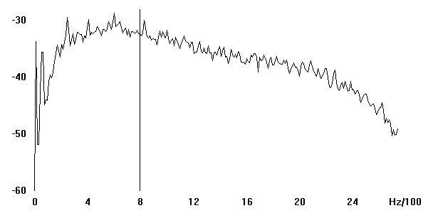
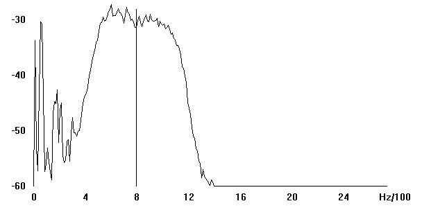
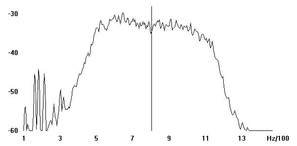
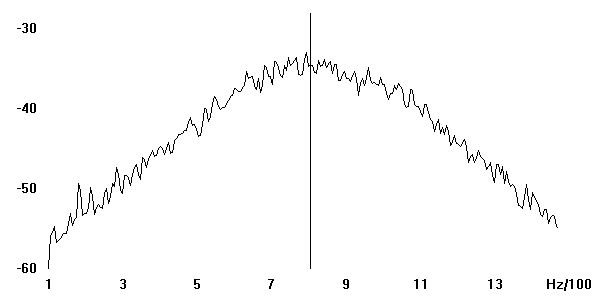
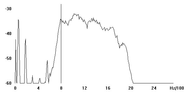
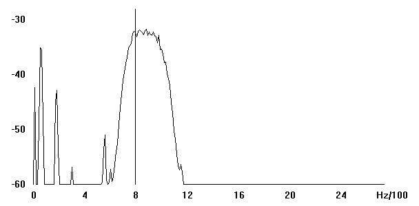
Below are some sample measurements of my equipment. The first graph shows the normal wide SSB filter of my TS-140. Note that for voice reception approximately 2 kHz bandwidth is needed so the filter is wide. This stock filter in my transceiver does have some high frequency roll off, but it is satisfactory for voice operation. In comparison note the response of the optional CW filter installed. This particular filter is a mechanical resonator filter operating at a 455 kHz IF. Also shown is a zoomed in view. Note this filter reduces the IF passband to approximately 600 Hz. This filter has very good stop band rejection, probably a virtue of this type of filter but it is not nearly as narrow as some crystal filters. Still its a great improvement for CW operating over the SSB filter!
Standard SSB Filter in TS-140
Mechanical CW Filter in TS-140
Detailed View of CW Filter in TS-140
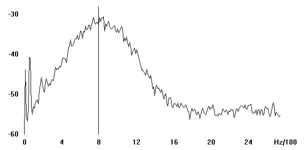
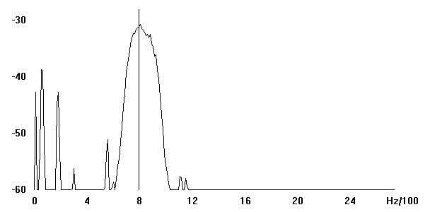
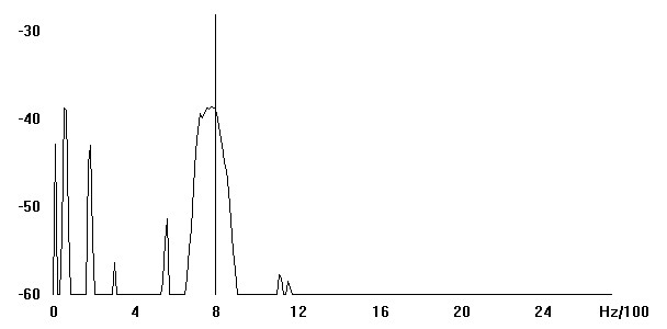
Here are some measurements of the crystal filter in my Tentec 1340 QRP transceiver. It is realized with 4 low cost crystals. When I built the kit I selected the 4 closest crystals within the 6 used in the kit, and overall i am pleased with the results. This filter does not have as much stopband rejection as the filter in the TS-140, but still it offers useful rejection with approximately the same bandwidth. Noteworthy is the cost of this simple filter - the entire kit cost less than the commercial filter in the TS-140.
Crystal CW Filter in TenTec 1340
Detailed View of CW Filter in TenTec 1340
Adjustable Crystal CW Filter in K2
Below are the four CW filter settings in the K2. The builder has the opportunity to set up four different bandwidths, which are then selectable as four filter settings - just like having four different filters in the rig for CW. The actual filter settings are realized by tuning varactor diodes located between the crystal stages in the filter.
Crystal CW Filter in K2 - 1.5 kHz Setting
Crystal CW Filter in K2 - 700 Hz Setting
Crystal CW Filter in K2 - 400 Hz Setting
Crystal CW Filter in K2 - 100 Hz Setting
Conclusions
The CW filter in the K2, even at its moderate bandwidth settings is clearly sharper than the filter within the TT1340. The latter kit does not come with matched crystals, and even though I had selected the closest four of six crystals, it does not come close to the capability of the K2. Still it is much better than not having a CW filter at all. The mechanical CW filter installed in the TS-140 is also inferior to the K2's crystal filter, but it still provides useful CW operating capability. Have fun checking out the filtering characteristics of your rigs!