3KV, 1A Power Supply
!! WARNING !!
Dangerous potentials and currents are present almost everywhere in this device
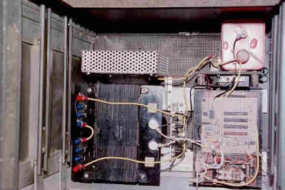
Overhead View
This is the conventional supply assembled in the Spring of '99 with a 3 KW (85 lb) Varian transformer and some csDC (that company was acquired some years back by HV Component Associates) diode assemblies had been resting for a long time.
The transformer & diodes (connected in FWB) connect to an 8 Hy 1A 10KV 30 Ohm DCR Westinghouse choke (50 lbs) resonated with .2uF, and a 40 uF / 5000 V Maxwell plastic filter capacitor and a 50000 ohm 400 watt bleeder (comprised of four 50K 100W resistors connected in series parallel mounted to a fiberglass plate and encased in cane metal).
The transformer and choke are mounted, with 1/4-28 bolts, to two aluminum bars of ½" by 2½" cross section which are affixed, again with 1/4-28 bolts, in turn to the bottom of the cabinet. The diode assemblies are mounted, with 8/32 screws, on a 1/8" aluminum plate which is vertically oriented, between the transformer and the choke, and is mounted to the bars with a couple of 10/32 screws through an L shaped foot bent into the bottom of the plate. The bleeder assembly is attached via four 8/32 screws and a pair of custom made brackets to the forward base bar. All of the above mentioned screws are installed in tapped holes.. There are no nuts used in the final assembly!
The above described assembly is mounted at the rear of the bottom of the cabinet to maintain a favorable center of gravity.
All the HV circuitry is connected with #16 bright yellow silicone 10KV wire that looks real cute. The transformer primary is connected with #10 Teflon wire.
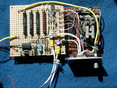
Metering & Control Closeup
The control and metering (Plate I & V sense resistors) circuitry is mounted on a piece of vectorboard which is screwed to the top of the choke. The is a clear plexiglass guard over all these parts.
The Schematic
There is an unusual step start circuit in this supply. The main power relay is in the control section which is mounted below the RF deck and above the HV supply.
The step-start relay (24 V, SPST, 25 A contacts) & resistor (20 ohm 250W but, not properly heatsinked for that rating) is mounted on top of the filter choke in the HV section. The relay is connected in series with (and driven by) the screen source which comes from the low end of the plate bleed as there was no control voltage handy in the HV supply. An SCR circuit enables the relay when there is 30 volts across the relay coil providing a very snappy contact closure, about a second after power up.
The step-start resistor is fused, just in case the relay, or the drive circuit, ever quits to avoid exploding the resistor. There is neon indicator adjacent to the step start which is lit when the step-start is complete... or blinks when/if the step-start fuse should open.
The screen supply is sourced from the low end of the conventional bleeder string, which has a 400 V SCR crowbar circuit protecting the screen source, just in case something should come loose between the HV supply and the control unit.
Finally, there is a safety HV indicator, (NE-2 blinky light circuit with 50M and a .1uF), connected directly across the HV mounted on top of the filter capacitor.