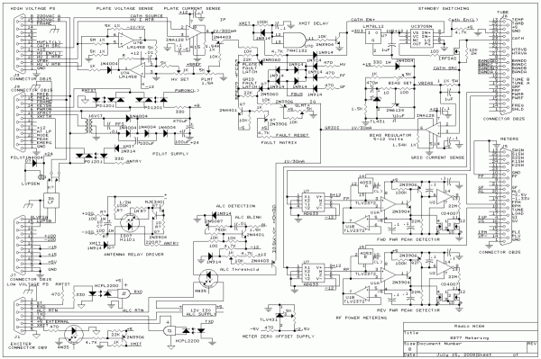
8877 Linear Amplifier Control Circuitry
Logic, Motor, & Heater Supply --
This is a commercial power supply providing +5 volts, +/- 15 volts and 48 volts. A modification to the output stage of this supply provides a 30 volt and a 100 volt source. The +5 volts is used for the tube heater in addition to the control logic.
Keying circuit --
A power FET is used to switch from standby to transmit in the cathode line.
Bias Generator --
A TL431A, with a current boost transistor, is used to establish the bias voltage. This bias is applied to the grid circuit rather than in the typical cathode location. A "keep alive" current is supplied from the +15 volt supply to maintain the required minumum current through this regulator in standby. Operation of the circuit shown has been verified up to two amps; Far in excess of the maximum grid current.
A drawing showing the above sections in concert may be seen here.
Grid & Plate Current sensors --
The Grid and Plate currents are sensed across small value resistors by integrated 3 op-amp topology instrumentation amplifiers. The operation of the peak detectors is the same as the circuit described at the bottom of the page displayed here.
Fault sensors: Grid & Plate -- Simple transistor comparators, with levels set by trimpots, connected to the grid and plate current sense lines trigger small SCR's in the fault matrix.
Fault Matrix -- A bit of diode logic which shuts down the cathode key line on any grid or plate current fault and also drives the front panel fault indicators.
ALC circuit --
The ALC is derived from the grid current metering rather than the traditional RF drive level sense.
Antenna Relay Drive -- The antenna relays are energized by an optoisolated current source.
Fwd & Rev Power Detectors + Peak detection -- The sensor voltages are squared by analog multipliers. The forward and reverse power meters may be driven directly from this point or selectively from a delayed release peak detector.
The operation of these peak detectors is identical to that employed at the bottom of the page displayed here
Pilot Supply--
Engaging the keyswitch powers the small pilot supply which enables the power switch and the remote start circuit.
Motor Drive --
Two speed servo controlled by the microprocessor.
Power Fail Sense --
The AC line is sampled to provide for an orderly shut down in the event of a power failure.
Preset Storage --
The microprocessor has 256 bytes of EEPROM which store the preset tuning values for each band as well as soft limits for the vacuum capacitors
Grid & Plate Current Peak Detectors -- The grid and plate current meters may be driven directly from this point or selectively from a delayed release peak detector.
The operation of the peak detectors is the same as the circuit described at the bottom of the page displayed here.
Metering --
The meters are all 5 volt (1K ohm/volt) intrinsic movements
Displays --
The lower two 3 digit displays show the current setting of the two quadrature encoded knobs.
The upper 3 digit display shows the current operation frequency.
An eight digit alphanumeric display at the top will provide mode information.
Knobs --
The two knobs are connected to quadrature encoders to set manual tuning and other functions.
The left knob is typically manual tune, the right manual load.
Switches --
Power on-off -- Alternately initiates a power on or power off cycle.
Peak hold -- Selects the peak hold function for four of the meters.
Autotune -- Initiates an autotune cycle: Detect input frequency, preset reactive elements, enable the amplifier, and tweak final tuning.
Mode --
An "Emergency Off" may be commanded by simultaneously pressing the power switch and any of the other three switches.
Pilot Supply --
Engaging the keyswitch powers a small pilot supply which enables the power switch.
