
The pi-net with a parallel feed plate choke has been problematic ever since the addition of the 15 meter band in the 1950's.
"RF Chokes for High Power Parallel Feed", an article by Vernon Chambers in the May 1954 issue of QST magazine, pp 30-33, covers the topic in detail. It suggested placing the dangerous series resonance around 25 Mhz in an 80-10 meter design. That was fine for the 1950's but, the 12 meter band is right there now! Append 160 meters to the other end of the problem and it's nigh insolvable.
Commercial Amateur (is that an oxymoron?) amplifiers sometimes use a switched, or relay selected, plate choke scheme to skirt this problem. There are more elegant options.
One alternative to parallel feed, as implemented in the Collins AM-1640(XW-1)/GRT, a 45KW continuous (2-30MHz) coverage amplifier with (4) 4CX5000A tubes in parallel, was to run both the RF and the DC plate feed through the pi-network. A simple diplexer connected at the output of the pi-net, with 18uH coils and 4000pF capacitors, easily separates the RF and DC feeds at this low impedance point without the possiblity of stray resonances. The substantial drawback to this arrangement is that both the tune & load capacitors must be rated for the DC voltage plus the RF voltage: 15 KV for the plate capacitor and 10 KV for the load capacitor in this example. These are large and expensive parts.
A similar example, in the amateur radio field, may be seen in "Some Notes on Grounded-Grid Linear Amplifiers", an article by Wayne Cooper in the August 1965 issue of 73 Magazine, pp 18-21 which shows a similar circuit to the Collins amp described above though with an unnecessarily oversize "plate" choke at the low impedance point. This design uses vacuum caps. The plate tune unit must be rated at 5KV operating (7.5KV test) even at the relatively low 2300 volt plate supply. Similarly, the load capacitor would need to be rated at 3KV operating (5KV test).
There was a "half-way" version of this concept presented in June '78 Ham Radio, p.98, which suggested placing the plate choke after the Pi coil and relocating the RF coupling cap to that point. This would work similarly in exchange for greatly increasing the current through, and the required value of, the "plate" coupling capacitor. As in the other schemes, the plate tuning capacitor needs to be rated at 2X the DC value. These are likely uneconomic tradeoffs.

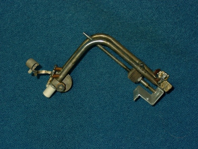
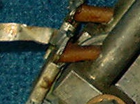
Another military solution was seen in a 2-36 MHz Hughes Aircraft airborne kilowatt amplifier that was designed circa 1958 for use in the B-58 bomber. This design used a length of RG-402 (seen at the upper left center coiling off into the darkness...) for fixed portion of the Pi coil. The center conductor was connected directly to the plates of the tubes and the plate blocking capacitor (horizontal by the top of the tube on the left) was connected in "conventional" fashion between the plate and the outer conductor of the semi-rigid cable which connects to the plate tuning capacitor. (via the teflon enclosed strap at a 45 degree angle to the upper left) The other end of the outer conductor of this coil was connected to the bandswitch and the lower frequency switched portion of the Pi coil. The center conductor of the output end was connected to the HV supply through the rather ordinary looking 1mHy choke of sufficient current capability.
When this arrangement is operating at it's highest frequency, the effective impedance presented at the top of the choke is only 50 ohms! At lower frequencies, a larger portion of the following Pi coil is engaged and the impedance at this point increases but, since the operating frequency is simultaneously decreasing the applied stress on the choke likely remains somewhat constant. No special ratings are required for the tune & load capacitors in this design. An amplifier employing a Pi-L output network would raise the impedance level somewhat though the stress on the choke would still be greatly lessened as compared to the conventional connection.
RG-402 is rated for 5KV DC, so this technique would be applicable to an amplifier with a 2500V plate supply. The method could be extended to higher power levels by employing RG-401 (7.5KV) or if that isn't available, just running some high voltage, high temperature (silicone) wire through a piece of copper tubing before winding the coil.
Taking the concept a step further, the entire Pi or Pi-L coil could be wound from RG402 to gain all advantages of the first mentioned Collins example without any of the drawbacks. I intend to try this approach in the 4CX600 amp which I'm currently building. To increase the Q of the Pi-secion of the coil on the higher bands, I'll place a section of 1/4" copper tubing over the 10 meter end of the RG-402 before winding.
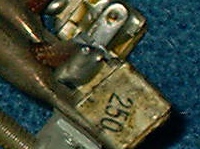
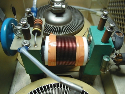
Motorola engineers were apparently aware of this scheme in the 1950's and applied it in a VHF mobile radio I just recently... inspected. This is a Push-Pull tuned line with the lower end of the line grounded. Looking at the photo below, you can see the plate feed on the left coupled to the line through a small metal clad mica cap. The DC feed enters the top of the line through a small hole and exits at the cold end, on the right, through another hole where it is effectively at AC ground potential and is directly bypassed to chassis ground, with another mica cap, and was connected directly to B+ with no RF choke.
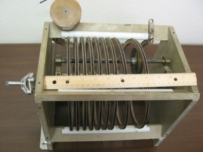
Unfortunately, due to space and insulation considerations, this trick isn't applicable to small roller coils but, I've seen a large Harris coil which implements the technique by running a wire down a slot in the outer edge while the roller rides on the inner edge.
A final option worth mentioning is the ferrite loaded RF Choke.
A homebrew example is disclosed in "A Unique RF Plate Choke" by Bill Deane.
A commercial example, employed in the Harris RF-110A, is shown below
Thanks to Phil, K5PC, for this photo.