Grid Regulator
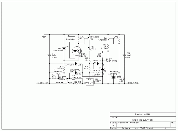
This control grid bias regulator may seem to be a mite complicated upon first viewing.
However, it is designed for electronic bias switching with an "on" transistion time less than 1mS.
It is also precision regulated, current limited and protected against reverse current.
No external power supply is required for operation and, if the input supply is floating,
no current other than the output current returns through ground to facilitate metering.
This basic design may be extended to 300 volts with upgrades in component types and
some changes in part values.
Regulator Circuit Description
Tracking Preregulator -- Q3 and its associated components comprise a preregulator
which limits both the voltage and current available to the main regulator.
Q1, Q2, R1 & R2 form a 1mA current source to drive the base of Q3,
the preregulator pass transistor.
The current through R2 is also used to bias the turn on circuitry.
Q4 and R4 limit the pass current at 30mA to protect against output shorts and
Q3 should be heatsinked for 5 watts to accomodate this condition.
D3 limits the voltage across U1 to 10 volts.
D2 provides protection to both U1 and Q3 from the stored charge in C3
in the event that the input supply is shorted.
Regulator -- U1 and its associated components form the main regulator.
R7 sets the reference current at 10mA. R5, R6 and RV1 set the regulated output voltage
with a nominal factor of 100 ohms per volt.
R6 sets the minimum enabled output voltage.
The output is normally off until Q5 is driven by ISO1 to ground the reference resistor chain.
The on and off times are typically 1mS and 10mS respectively, though these will vary with
the total voltage excursion being current sourced in both directions.
D1 limits the off voltage across ISO1 to a safe value.
If an "off" voltage which is a differential from the enabled value is desired
(less than the full input supply),
it may be set by adding a resistor from the collector of Q5 to ground.
Note: The LM337 pin numbers shown are for the TO-39 package;
The pin assignments vary on other packages.
Smart Bleeder -- U2, Q6, & Q7 plus their associated components make up the smart bleeder.
R10, C2 and D5 bias the base of Q6 at 10 volts above the output rail.
When the supply is commanded to slew to a less negative value (grid enable),
the current through R6 & R7 will exceed the nominal 10 mA and
develop a voltage greater than 2.5 volts, above the output rail, at the junction of R5 & R6.
This will turn U2 on which will drive emitter follower Q7.
The current through the smart bleed is set by R8 at 300mA.
D4 clamps U2's reference input just above 2.5 volts to prevent... trouble.
Note: If a substitution is made for Q6, ensure that the replacement part
has sufficient second breakdown capability for 300mA at 100V for 1mS.
