A log-cell fed Yagi for the FM Broadcast Band
During sporadic E openings FM broadcast band signals come in here from the Pacific Islands, in particular from Fiji (88.2, 89.2, 89.4), Tonga (87.5, 88.1, 88.6) and New Caledonia (88.0, 89.0, 90.0). Unfortunately very strong local FM band signals from several high power transmitters between 90 and 101.5 MHz on a mountain top 35km away tend to overload my wide band SDR receiver and produce undesirable responses on the waterfall ... but the Pacific Islands DX stations are generally north of here and the local stations are south, so a directional antenna pointed northwards with a good F/B over a wide frequency range would help fix the problem.
Using 4NEC2 antenna modelling software, a 5 element log-cell fed Yagi was designed which provided >20dB F/B ratio over most of the 88 to 108 MHz FM broadcast band. The forward gain figure is not high (about 7.7dBi), but because the objective was to reduce local QRM and receiver overload, a good F/B ratio over a wide bandwidth was the important parameter.

The log-cell FM band Yagi was built on a 1.25m length of 25mm square aluminium boom using 10mm diameter aluminium tube elements and mounting insulators from the TV industry. A short mid-boom 'stiffener' (250mm of 25mm square tube) was used to allow the mast clamp to be mounted below the boom so the mast will not contact the middle element's insulator.
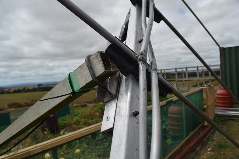
Mid-boom stiffener and mast clamp
The log-cell section is fed with a 'Grounded Coax Quarter Wave Line' balun design taken from DG7YBN's web site. The ferrite sleeves used at the feed point were on hand from my junk box and more suited to low HF frequencies, but still provide a few hundred Ohms of impedance at VHF to help suppressing RF on the outside of the 1/4 line. Anyway, from past RF current measurements on 6m and 2m band Yagis using this style of 1:1 balun, the 'grounded 1/4 wave line' part of the balun assembly is doing most of the work in 'symmetrising' (balancing) the feed point and the ferrites are not really even necessary.
The phasing lines between the log-cell elements were made from thin-walled 10mm diameter aluminium tube spaced at about 17mm center to center which, according to the simplified equation for parallel line impedance, should be close to the desired 140 Ohms. They were curved/bent to provide the required center-to-center line spacing dimension and cut to fit the gaps between the log cell elements, then the ends were flattened and drilled for mounting/fixing with self tapping screws.
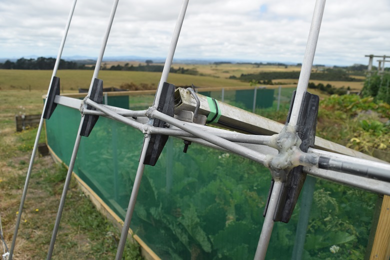
Balun and phasing lines
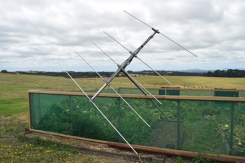
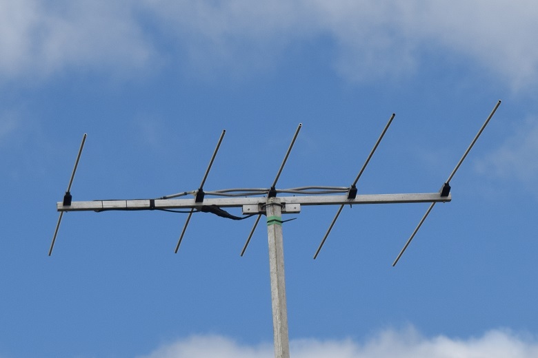
The finished log-cell fed Yagi for the FM broadcast band
Temporarily mounted at 5m high on a length of 30mm square aluminium tube
In the immortal words of the great Dame Edna Everage ... "Hello Possum!"
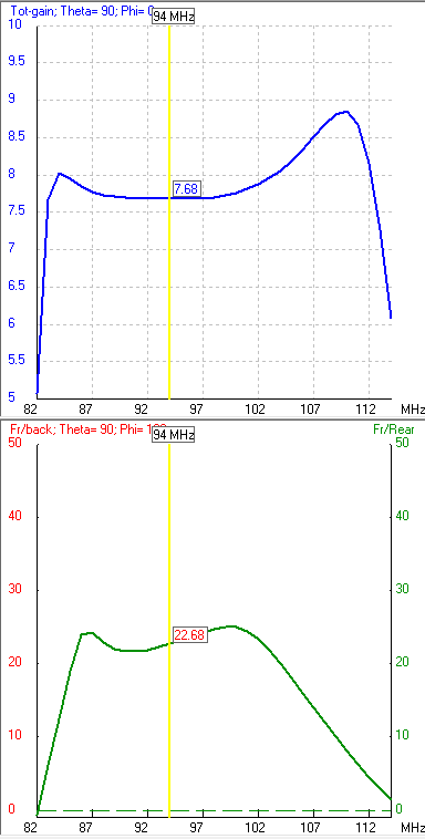
The log-cell FM Yagi's forward gain and F/B curves from 82 to 113 MHz

Radiation pattern at 88MHz
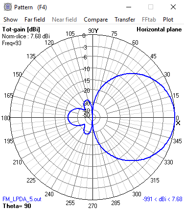
Radiation pattern at 93MHz
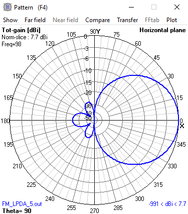
Radiation pattern at 98MHz
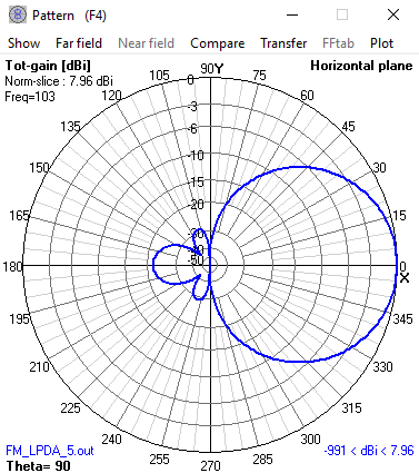
Radiation pattern at 103MHz
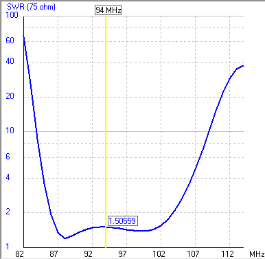
75 Ohm SWR curve across the FM band
|