Having just begun my Raspberry Pi journey and finding a DTMF decoder chip at a surplus store I was inspired to try my first piece of wireless automation. Dual Tone Multi Frequency is a very simple analog signaling method which a pair of audio signals is used to encode any one number at a time between 0 and 16: the numbers 10-16 being used to represent the characters ‘A, B, C, D, #, and *’. This was one of the first steps in fully automated phone networks, as telephone switchboards recieving these tones from a 'touch tone phone' could know which number to dial without a human operater making the connections.
DTMF is still used in HAM radio, mostly for controlling repeaters and some remote stations.
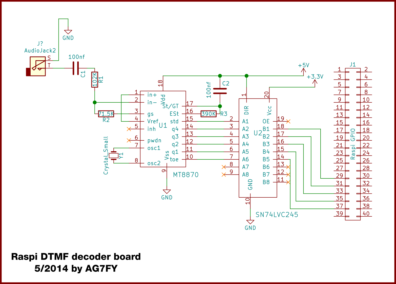
The circuit is mostly from the 8870 datasheet. A 3.57Mhz ‘colorburst’ crystal is used to drive it’s oscillator, followed by some audio buffering circuitry. Being an older CMOS device these chips run on 5volts, so a SN74LVC245 is used for dropping the voltage down to 3.3v for the Raspberry Pi pins. I happened to have one of those, but for the very slow signal speeds we’re using here I’m pretty sure a 1k-2k resistor voltage divider would step the voltage down without any problems. All it needs is audio from any radio. A Baofeng Uv-5R would be a great dual-band option. I myself am using an old Icom T-22 as a receiver. No reason this circuit wouldn't work with an actual phone, or maybe even some kind of wired intercom setup.
This circuit had started on a breadboard with an old Archer Electronics decoder, but I made a mistake shorting some outputs to ground and fried it. It worked out ok though, because the MT8870 is a pretty common chip still available from a lot of sources.
Current version of the DTMF decoder script is here: gitlab.com/motivemachine/dtmf-decoder-board
Finally we are on to the programming. With the amount of time it took me to get back to this project I had the change to do some more reading of GPIO documentation and learned of the new (at the time) 'wait for event' functions. A loop called in the gpio module that halts the python program until an event is detected, in this case the rising/falling edge of a GPIO input. I now know of a much better way than polling to determine if a valid DTMF code has been received by the 8870. This new knowledge will also give me a chance to rework the code and update it for the new chip.
The primary difference between the old Archer chip and the 8870 is that the Archer's outputs toggled HIGH only as long as the tone pair was being received. 40ms after the tone pair was no longer available, all outputs reverted to LOW state. With the 8870 chip only the steering/signal pin (pin 18 if you're following along with the datasheet) is toggled as the signal comes and goes. The four binary output pins of the chip itself are latched in their HIGH/LOW states until another tone is detected; that is the output does not return to zero between DTMF tones, it merely remembers the last input.
Once the flag pin goes HIGH, the Pi is reading the four binary input pins and adding this to a list. The 'list of lists' being built is 4 binary numbers, 4 bits each. Currently is just supports a 4 number code. Once the list is complete, a function iterates each binary number back to decimal, and we have a list of the numbers we sent from the keypad.
The '*' key (binary 11) is serving as our enter button. It has two jobs: tell the program our entry is complete and find out if it matches a valid command. If the '*' appears before the end of our list, it simply clears the list. This prevents a scenario where one number is missed by interferance or a light key-press, leaving us in an endless loop of partially complete lists that can never be properly decoded. If one code entry does not appear to work, press '*' once or twice to be sure the list is clear, and try again.
The very last if/elif series simply compares recieved codes to see if any of them should lead to doing something. Anything is possible here. Currently they just display different print statements as testing, but you can insert code to toggle a relay, control a repeater, open a garage door, whatever you need. Perhaps with a PTT switch connected to the radio and a speak output you could have espeak read you a weather report over the radio!