编者:本文是从一个日本的无线电爱好者的网页上摘引过来的,原文有日语和英语两版本,我们去掉了日语部分。

Simple television receiver
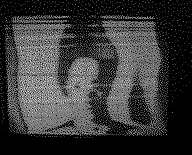
When I made FM radio, I could hear the voice signal of first channel of TV. On the frequency slightly lower than that, I could hear the noisy signal of picture of TV. My oscilloscope has Z input. It can display black and white. I made the simple TV receiver. It displays the picture on my oscilloscope.
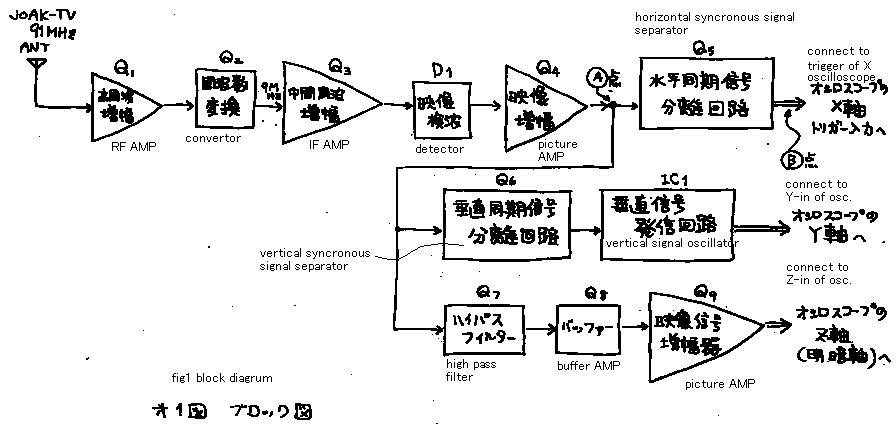
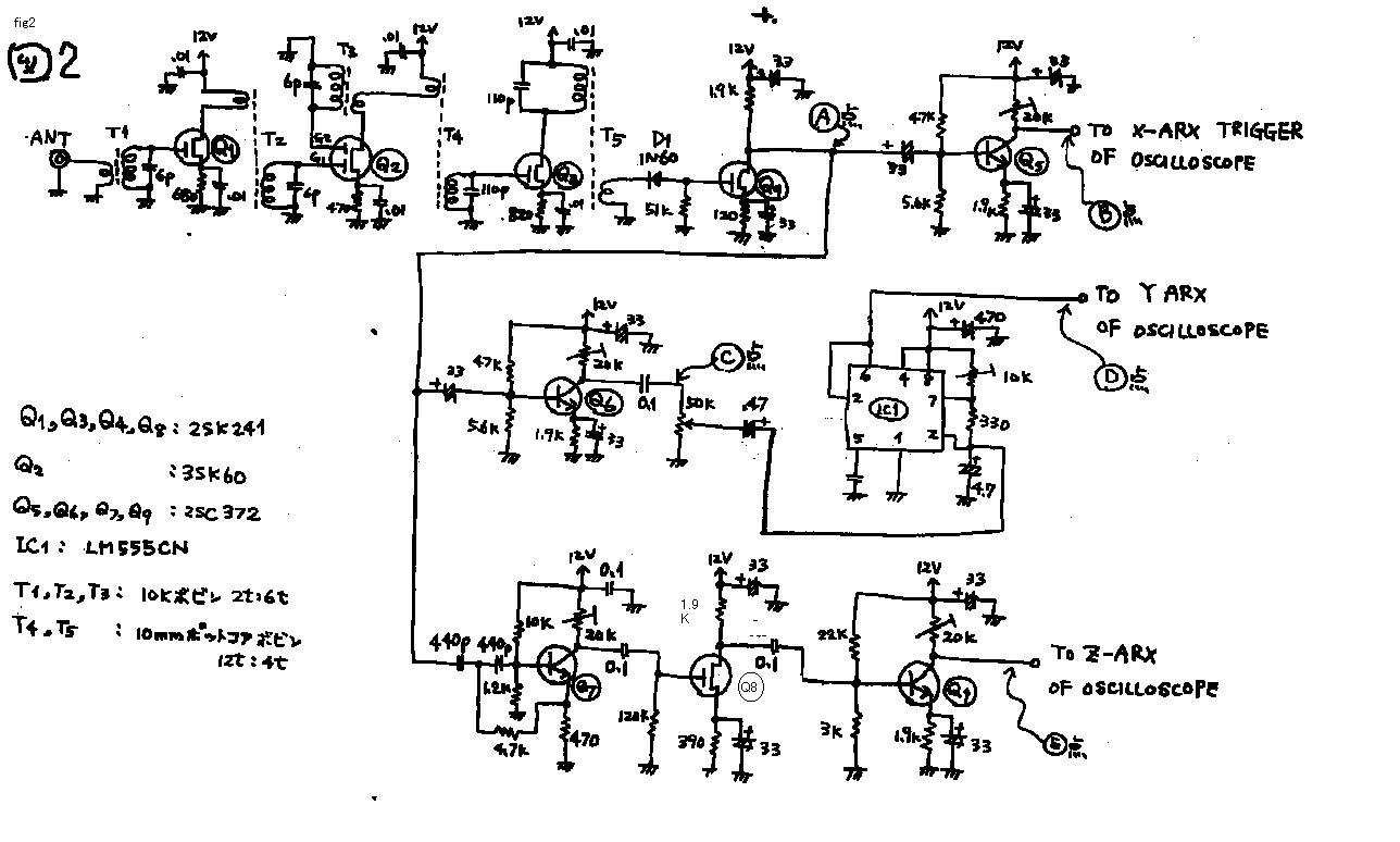
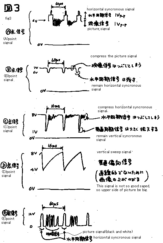
See fig 1! The signal (comming from the antenna) is amplified and detected. It has the same circuit as a FM radio. But detector of it is amplitude modulation detector. This radio do not have tune control. This machine is able to receiv only the first channel. Receiving frequency is tuned by core of T3. On the (A) point of fig2, I can watch the TV signal indicated on the textbook. See fig 3! I show you the (A) point signal. (A) point signal includes picture signal and horizontal synchronous signal and vertical synchronous signal. Each signals are separated by the signal separator. The famous oscillator IC (555) products the vertical sweep signal. And it is synchronized by the separated synchronous trigger signal. Z input of oscilloscope indicates only black or white. It can not display the gray. It is TTL level input. Therefore the picture on the oscilloscope is only yes or no. It can indicates only the outline of the picture. The Brown tube of oscilloscope is not so bright as that of sold TV set. So I must look it on the dark room.
I could enjoy to make this machine. If you are tired to make radios, make TV!
Discription add on 10 Dec 98
Iliyan send the following E-mail. 10Dec98
I also made oscilloscope TV like you, but I used 4 resistor (1k,2k,4k,8k) based DAC to modulate the beam - I mean pulse modulation for 16 shades of gray intensity. It was disappointing, because the brightness of the oscilloscope tube is not good to watch during the day! What do you think about my projects? If you want to make them, you can also put them on your home-page - I will be very happy! As I said, it was almost 20 years ago, when I did it, so I do not have the original diagrams. The three major components were CMOS Hexadecimal Buffered Counter with build-in clock (500khz), 4 x resistors connected to buffers, and Voltage Comparator. The principal was very easy - counter starts counting clock impulses and as soon as the voltage coming from the receiver is equal to the voltage, produced by the resistors, comparator sends reset to buffers, and everything starts again from the beginning. The output of the counter was also fed to the PCM modulator of the Z input of my oscilloscope.

Pic 1

Pic 2

Pic 3
