nRF24L01 Notes by DL4YHF
Original file location: ?/datasheets/PLL_and_RF_Special_ICs/nRF24L01/DL4YHF_nRF24L01_Notes.htm
Link to the website: www.qsl.net/dl4yhf/nRF24L01/DL4YHF_nRF24L01_Notes.htm
/ back to the index.
The nRF24L01(+) attracted the author's attention because it's widely available
on a small module with either an antenna printed on the PCB, or even
with a small on-board "power amplifier" / "low noise amplifier".
A couple of those development boards was ordered from a various suppliers,
with qualities ranging from 'non-functional crap or fake chips' to 'perfect':
The module with 'PA + LNA' draws significantly
more DC current that then 'bare' "nRF24L01+" module (without the bidirectional
amplifier chip). Thus, for the planned "QRPP 13 cm CW beacon",
some bare modules were ordered, too. On the second attempt, a seller (AZ-Delivery) was found
who really had the PCB populated with a genuine nRF24L01+ chip.
- nRF24L01 General Info and locally saved datasheets
- nRF24L01(+) Datasheets
- nRF24L01 Info Links
- nRF24L01 Hardware, Host Interface, Pinouts
- nRF24L01 Continous Wave Mode (e.g. beacon or signal generator)
- Registers to control CW mode, power, frequency
- QRP Beacon Firmware (using an 8-bit PIC)
1. nRF24L01(+) General Info and locally saved datasheets
Difference between both chips (with and without the "+" suffix),
The nRF24L01 is a single-chip wireless transceiver chip produced by Nordic Semiconductor.
Its radio frequency band is between 2.4GHz and 2.5GHz. This frequency band also belongs
to the license-free ISM (Industrial, Scientific and Medical) ...
There are modules such as nRF24L01 module, nRF24L01+ module, nRF24L01+ PA/LNA module.
They are actually similar, nRF24L01+ is an upgraded version of nRF24L01 chip.
nRF24L01 only supports 1Mbps and 2Mbps transmission rate,
while nRF24L01+ also supports 250Kbps transmission rate.
The '+' variant features a lower data rate mode, superior sensitivity,
better regulatory compliance, and increased communication reliability.
The nRF24L01+ PA/LNA module is an external antenna signal module that integrates
transceiver amplification on the basis of the nRF24L01+ module, which increases
the transmission distance of the module. In an open environment, the maximum
transmission distance of the nRF24L01/nRF24L01+ module using the on-board PCB antenna
is only 100 meters, while the PA/LNA module can reach 1000 meters.
1.1 nRF24L01(+) Datasheets
- nRF24L01+PA+LNA 2.4GHz RF Transceiver Module.pdf
- From 'Handson Technology':
This module based on Nordic nRF24L01+ with integrated Power Amplifier (PA)
and Low-Noise-Amplifier (LNA) for extended range of up to 1,000 meter.
This transceiver IC operates in the 2.4GHz band and has many new features!
Take all the coolness of the nRF2401A and add some extra pipelines, buffers,
and an auto-retransmit feature. You can use it in you project without any
wireless design, just need to leave a 8 pins interface to this module,
use the SPI interface to control the module on transferring data.
- nRF24L01plus_Product_Specification_1_0.pdf
- Sheds some light on difference between the "+" and "non-plus" chips:
nRF24L01+ is drop-in compatible with nRF24L01 and on-air compatible with nRF2401A,
nRF2402, nRF24E1 and nRF24E2. Intermodulation and wideband blocking values
in nRF24L01+ are much improved in comparison to the nRF24L01 and the addition
of internal filtering to nRF24L01+ has improved the margins for meeting RF
regulatory standards.
(draw your own conclusions about 'meeting RF regulatory standards' of the "non-plus" chips..)
Also, only the nRF24L01+ supports the low 'air data rate' (250 kbps)
used in the QRP Beacon Firmware.
- NRF24L01_old_preliminary_product_specification.pdf
-
- nRF24L01 Product Specification V2.0 (anno 2007)
-
1.2 nRF24L01 Info Links
- https://forum.arduino.cc/t/simple-nrf24l01-2-4ghz-transceiver-demo/405123
- Introduction to the RF24 library
- https://github.com/nRF24/RF24/blob/master/COMMON_ISSUES.md
- Contains helpful notes for troubleshooting with the 'RF24' class driver from Github, e.g.:
My PA/LNA module fails to transmit
You may find variants of the nRF24L01 transceiver that are marketed as
"nRF24L01+PA+LNA" (WB: The ones used here). These modules are distinct
in the fact that they come with a detachable (SMA-type) antenna.
They employ separate RFX24C01 IC with the antenna for enhanced
Power Amplification (PA) and Low Noise Amplification (LNA) features.
While they boast greater range with the same functionality,
they are subject to a couple lesser known (and lesser advertised) drawbacks:
- Stronger power source (...)
- Needs shielding from electromagnetic interference.(...)
My PA/LNA module doesn't perform as well as I'd hoped or the NRF radio works better on touching it
As described above, the radio modules (notably the PA+LNA versions)
are reliant on a stable power source. While these modules may work
with a poor power supply, they often lose packets or fail to receive
as many as a module with a better power source. Moreover, this can
sometimes be seen in odd ways such as the radio module working better
when touched. This again is likely a power stability issue because
the radio module is missing a capacitor (a commonly neglected expense
on behalf of the module's manufacturer).
Add capacitor(s) close to the VCC and GND pins of the radio.
Typically, 10uF is enough. Depending upon your circuit's layout,
differences in capacitors' electrolytic properties can be seen,
such that a low ESR (Equivalent Series Resistance) rated capacitor
is desirable.
2. nRF24L01 Hardware, Host Interface, Pinouts

Interface pinout of the 'nRF24L01+ PA/LNA' board (top view, from the 'Handsontec Transceiver Module)
Since none of the originally purchased 'nRF2401+ PA/LNA' boards
was working properly (*),
it was time to take a "closer look" at the board. So here it is, with the IC pins numbered (red)
and some important signal lines (PCB traces marked white):

Layout of the 'nRF24L01+ PA/LNA' board. Click on image to magnify.
Many of these boards floating around the planet are crap (*).
The (faulty) PA/LNA is a Skyworks RFX2401C "2.4 GHz Front-End Module", SMD part marking "2401C".
The datasheet is widely available. Pins on the 3*3 mm QFN-16 IC are:
                          Vdd NC Vdd DNC
                       ,-----------------,
                       | O 16 15  14 13  |
                    NC |1    ......... 12| NC
                       |    .        .   |
                   GND |2  .  (17)   . 11| GND
                       |   . GND/    .   |
                   GND |3  . COOLING!. 10| ANT <----> to/from PI-filter <---> Antenna
                       |   ...........   |     RX  TX
           <----> TXRX |4               9| GND
           RX  TX      |   5   6   7  8  |
                       '-----------------'
                         TXEN RXEN NC GND    __
                           |   '------------|__|--<-- from nRF24L01+ "CE" (H=ChipEnable)
                           |                 __
                           '----------------|__|--<-- from nRF24L01+ "Vdd_PA" (H=TX, L=RX)
                        Skyworks RFX2401C    (resistors should be 10 k, but were populated with 1 kOhm)
  Note: "NC"  = Not Connected,
        "DNC" = "Do Not Connect" !
- About the non-functional boards from a German reseller:
- Three of the four boards had a dead nRF24L01+, easily identifyable
by measuring the impedance between MISO and ground before
powering on the device, which was around 45 Ohm.
The only board with a working nRF24L01+ (transceiver) had a dead "PA/LNA" (power amplifier/
low-noise amplifier for reception), and produced a maximum output
of -3 dBm at the highest power setting.
Above: Larger board with integrated PA (power amplifier for TX) and LNA (low-noise amp for RX).
Below: Smaller board with integrated antenna (printed to the PCB), without amplifiers.

Interface pinout of the 'nRF24L01+' board without "PA/LNA", but with on-board antenna.
Maximum output = 1 mW, thus only for short-range experiments. SPI adapter is compatible.
Unfortunately the first 'nRF24L01+' boards were NOT populated with
an nRF24L01+, but with the older nRF24L01 (without "+"). So it was unusable
as a low-power "CW beacon", and it doesn't support the long-range "low" speed
with 250 kBit/second.
The author had more luck on the second attempt, this time with modules from
a different reseller in Germany (AZ-Delivery, but that seller went out of business in 2026):

Foto of what the author believed was a 'genuine' nRF24L01+
on the 'black board' with integrated Meander-style PCB antenna.
The board with this chip produced the spectrum shown below.

Spectrum and Power Test from a "black board" with integrated Meander-style PCB antenna.
-47 dBm measured via DSA with a dipole antenna - see details about the test setup below.
For the above "Power Test" of the PA-less module, the receiver (DSA = Digital Spectrum Analyzer)
was located 50 cm away from the board, using a 2.4 GHz swivel dipole antenna (10 cm long)
from the "nRF24L01+PA+LNA" boards. The nRF24L01+ was configured for Continuous Wave,
and 1 mW output (the maximum), using the author's QRP CW Beacon
firmware running on an 8-bit PIC.
Peak power : -47 dB
Peak frequency: 2.40195 GHz.
During the first minute after power-on, frequency drift could be seen
on the DSA, even at a display span of 500 kHz. This is caused by the cheap 16 MHz crystal
being heated up (very moderately) by the nRF24L01+. Not an issue for wide-band FSK transmissions
at the chip's supported bitrates (500, 1000, and 2000 kBit/second), but too unstable
for serious 'narrow band' modes like CW / Morse code in amateur radio...
... but besides that, trying a CW QSO via the geostationary satellite QO-100
using an nRF24L01+ with "PA" (RFX2401C) and a tweaked 16-MHZ crystal would be fun !
(more on CW mode, and its applications in chapter 3)
2.1 nRF24L01(+) Pin Functions
From the nRF24L01+ datasheet (Rev 1.0, page 11):
| IC PIN | BOARD PIN | Name | Pin function | Description |
|---|
| 1 | 3 (!) | CE | Digital Input | Chip Enable Activates RX or TX mode |
| 2 | 4 (!) | CSN | Digital Input | SPI Chip Select |
| 3 | 5 (!) | SCK | Digital Input | SPI Clock |
| 4 | 6 (!) | MOSI | Digital Input | SPI Slave Data Input |
| 5 | 7 (!) | MISO | Digital Output | SPI Slave Data Output, with tri-state option |
| 6 | 8 (!) | IRQ | Digital Output | Maskable interrupt pin. Active low |
| 7 | 2 (!) | VDD | Power | Power Supply (+1.9V - +3.6V DC) |
| 8 | 1 (!) | VSS | Power | Ground (0V) |
2.2 nRF24L01(+) Host Interface
The nRF24L01(+) datasheet doesn't explicitly specify the SPI "mode".
So which of the four "SPI Modes" ( 2 * CPOL + CPHA) does it use ?
| Mode | CPOL | CPHA | SCLK Idle | Data Sampled On | Data Shifted On |
|---|
| 0 | 0 | 0 | Low | Rising Edge | Falling Edge |
| 1 | 0 | 1 | Low | Falling Edge | Rising Edge |
| 2 | 1 | 0 | High | Falling Edge | Rising Edge |
| 3 | 1 | 1 | High | Rising Edge | Falling Edge |
From the nRF24L01+ datasheet (Rev 1.0, page 52):
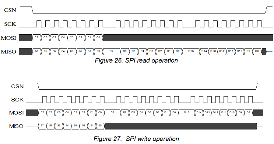
nRF24L01+ SPI read- and write operation. C7..0=COMMAND, S7..0=STATUS, D15..0=DATA.
-> Looks like "SPI Mode 0" (CPOL=0, CPHA=0):
Clock low on idle, data sampled on rising edge, data shifted on falling edge.
3. nRF24L01(+) Continous Wave Mode (e.g. beacon or signal generator)
From a thread at www.eevblog.com/forum/rf-microwave/zero-effort-2-4ghz-cw-beacon-with-switchable-frequency:
nRF24L01+ (which is dirt cheap) has a CW mode, with programmable CW frequency
and amplitude. Used that a couple of times, mostly as a quick sanity check
for SDR + Rx antenna + cable integrity. Though, it will take some time to wire,
to power and to program a chip.
(...)
There are ready made modules with nRF24L01+ and a PCB antenna.
Some modules also have an UFL connector, for an external antenna if needed.
Note that there are some nRF24L01 (without the + at the end).
I've tested the CW mode only on the nRF24L01+.
Then, you'll need a microcontroller to talk with the nRF chip.
Most common and cheapest would be an Arduino Nano board.
Can be bought ready made from any maker's shop, ebay, etc.
Probably they are at mouser or Digikey, too, but I never searched.
Both modules come with 0.1'' pins. Wire them together with some
DuPont wires, or solder them on a test board, and that's it.
For the software part, the CW mode for the nRF chip is documented
in its manual, so there are plenty of ready made Arduino examples
to put the nRF24L01+ in CW mode. Connect the Arduino to a PC,
download the demo, and it should work.
For a ready made program, search for 'nRF24L01 continuous carrier Arduino'. Random example:
https://forum.arduino.cc/t/nrf24l01-arduino-trying-to-get-constant-carrier-wave-output-for-testing/322112/13
continuous_carrier/continuous_carrier_Pv1.ino
Essential code (all in the Arduino-dictated "setup()"):
SPI_RW_Reg(WRITE_REG + CONFIG,0x0a);  // 1. Set PWR_UP = 1 and PRIM_RX = 0 in the CONFIG register.
       // Bit0:PRIM_RX:0(PTX) Bit1:PWR_UP:1(Up) Bits2-3:CRC:00 Bits4-6:IRQ:000 Bit7:Always0

  ... delays between register accesses omitted for clarity ...

SPI_RW_Reg(WRITE_REG + RF_SETUP,0x93); // 3. In the RF register set: CONT_WAVE = 1, PLL_LOCK = 1, RF_PWR.
       // bit0:LNA_HCURR:1, bits1-2:RFPwr:11(0dBm), bit3:DataRate:0(1Mbps), bit4:PLL_Lock:1, bits5-6:00, bit7:CONT_WAVE:1

SPI_RW_Reg(WRITE_REG + RF_CH,0x05);    // 4. Set the wanted RF channel.


digitalWrite(CE,1);  // 5. Set CE high.
                     // 6. Keep CE high as long as the carrier is needed.
See also (related to sending "CW" or even Morse Code with an nRF24L01+):
QRP Beacon Firmware (using a PIC)
3.1 Registers to control CW, power, frequency
Details about CW, frequency- and power control, from the
nRF24L01+ datasheet (Rev 1.0, page 58):
| Addr | Mnemonic | Bit | ResetVal | Type | Description |
|---|
| 05 | RF_CH | | | | RF Channel |
| | Reserved | 7 | 0 | R/W | Only '0' allowed |
| | RF_CH | 6:0 | 0000010 | R/W | Sets the frequency channel |
| | | | | | |
| 06 | RF Setup | | | | RF Setup Register |
| | CONT_WAVE | 7 | 0 | R/W | Enables continuous carrier transmit when high |
| | reserved | 6 | 0 | R/W | Only '0' allowed |
| | RF_DR_LOW | 5 | 0 | R/W | Set RF Data Rate to 250kbps.
See RF_DR_HIGH for encoding. |
| | PLL_LOCK | 4 | 0 | R/W | Force PLL lock signal. Only used in test |
| | RF_DR_HIGH | 3 | 0 | R/W | Select between the high speed data rates.
This bit is don't care if RF_DR_LOW is set. Encoding:
[RF_DR_LOW, RF_DR_HIGH]: |
| | | | | | '00' : 1Mbps |
| | | | | | '01' : 2Mbps |
| | | | | | '10' : 250kbps |
| | | | | | '11' : Reserved |
| | CONT_WAVE | 2:1 | 11 | R/W | Set RF output power (TX) |
| | | | | | '00' : -18 dBm |
| | | | | | '01' : -12 dBm |
| | | | | | '10' : -6 dBm |
| | | | | | '11' : 0 dBm |
| | obsolete | 0 | | | Don't care |
About what NORDIC call the 'frequency channel':
Frequency in MHz = 2400 + channel number in register 0x05, bits 6..0 .
Thus the only possible "CW carrier frequencies" are 2400 to 2525 MHz, in 1 MHz steps.
3.2 QRP Beacon Firmware (using an 8-bit PIC)
To test the range of a radio link based on the nRF24L01+, a firmware was developed
for the homebrew-friendly, extremely power-saving PIC16F628A (later adapted
for a PIC16F1847, which supports in-circuit debugging,
and a PIC18F25J50 with a native USB interface).
The inital 'range tests' in Continuous Wave mode used a software defined radio
(Adalm Pluto + SDR Console) and a narrow filter. To also test the real radio range
with digital data (32-byte packets sent at 250 kbit/second), the beacon
controller now sends "digital data" besides Morse code.
Details about the beacon control firmware may still exist on the author's website ...
www.qsl.net/dl4yhf/nRF24L01/nRF24_Control/Documentation/DL4YHF_nRF24L01_Control.htm
... or (local link, only works on the author's machine) in the beacon firmware project folder,
?/pic/nRF24_Control/Documentation/DL4YHF_nRF24L01_Control.htm .
