|
110-Ohm-Delta-Loops for 2 m, 4 m and 6 m (DK7ZB) (6-m-Delta-Loop for 50 Ohm see down)
|


|
|
110-Ohm-Delta-Loops for 2 m, 4 m and 6 m (DK7ZB) (6-m-Delta-Loop for 50 Ohm see down)
|
| The Delta-Loop has the parts B longer then A. The reason is a
little bit higher gain and an impedance of 110 Ohm. The
transformation to 50 Ohm is made with a quarterwave section of
75-Ohm-cable RG59 B/U. The spreader is a PVC-pipe with 25 mm
diameter. The wire is PVC-insulated copper braid 1,5 mm2. In the right picture you see two current maxima, the loop is a stacked system with a gain of 0,95 dBd. If the loop is configured for 100 Ohm we get a great bandwidth. The wires 2 and 3 are a little bit longer as wire 1 in that case. |
 |
 |
 |
 |
 |
![]()
50-Ohm-Delta-Loop for 50 MHz

 |
The normal Delta-Loop has an equilateral triangle, it has
an impedance of 115 Ohm and a great bandwidth (1 MHz for SWR <
1,3). If we make the vertical wires
longer and the horizontal wire shorter (isosceles triangle), we
can reach a relation which leads to an impedance of 50 Ohm. The
gain is increasing a little bit (from 0,95 dBd to 1,3 dBd). So
we do not need a matching section and we can feed the Delta-Loop
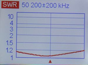
with 50-Ohm-coax directly. A simple common-wave choke is wound with 10 1/2 turns of coax-cable with 5 mm diameter on a 50-mm-PVC-tube. The bandwidth is smaller and the circumference more critical. My antenna has a SWR < 1,3 between 50,0 and 50,5 MHz. I have built the 50-Ohm-Loop with 1,5 mm2-PVC-insulated copper-wire and a circumference of 612 cm. Other wires need a complete other length! But it is not complicated to tune the length of an individual wire (insulated or not insulated) with an SWR-meter. Here SWR with 5 m coax:
|
SWR measured in the feedpoint:


If the antenna is mount with a feedpoint-heigt of 10 m above ground we get a elevation diagram as follows: