Übrigens... Ein kompletter Teilesatz ist noch da, bei Interesse bei mir melden...
BTW... There is still one complete set available, if you are interested,
just drop a note...
D: Zwei gekoppelte Endstufen mit jeweils 2 Stück 2C39 erzeugen ca. 400W HF.
E: Two coupled PAs with each 2 times 2C39 deliver around 400W RF.
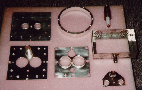
| Picture: All parts are silver plated
Übrigens... Ein kompletter Teilesatz ist noch da, bei Interesse bei mir melden... BTW... There is still one complete set available, if you are interested,
just drop a note...
|
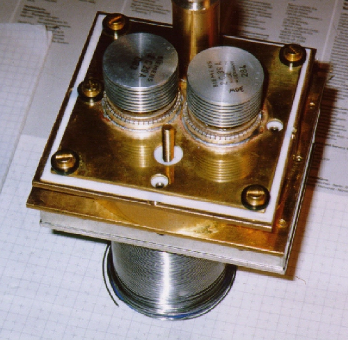
Picture: The complete unit before silver
platening
|
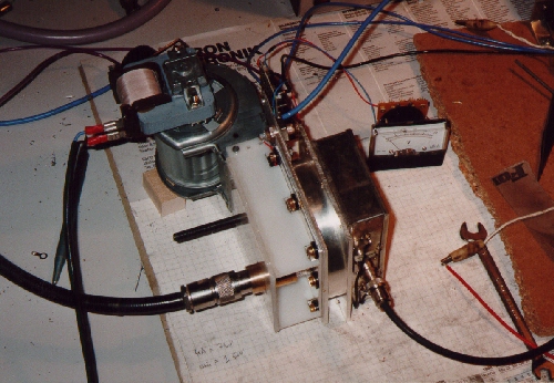
| Picture: Unit in operation
|
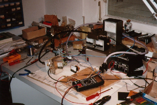
Picture: Test setup
|
D: Und so ist alles aufgebaut: Ein Tisch im Dachboden mit meinem 23cm-Transverter und der Sendeendstufe. Unter dem Tisch das Netzteil und eine große Kondensatorbatterie, die den viel zu kleinen Trafo stützen soll. Im dritten Foto erkennt man den Fuß meiner 70cm und 23cm Tropo-Antenne. Da manchmal Wasser durchkommt, steht dieser in einer Waschschüssel. Diese wiederum ist undicht, also wird das Wasser in einer Chemieschale aufgefangen und ab und zu geleert.
E: This is
how all is assembled: A table just below the roof with my 23cm transverter
and the power amplifier. Below the table you will see a battery of capacitors
which should support the much too small transformer.
 |
 |
 |
D: Diese Endstufe wird von
DC3CT (Fa. EME K. Müller gefertigt und stellt eine typische Topfkreis-Parallelschaltung
mit 12-15dB Gain dar.
E: This power amplifier
is produced by DC3CD (EME K. Müller company) and represents a typical
parallel circuit cavety with 12-15dB gain.
Schaltungsbeschreibung / Description of the Circuit:
D: Die Ansteuerleistung wird über C1 (das als Fest-C von ca. 500pF ausgelegt sein kann) an den Kathodenkreis angekoppelt. Eine Gewindestange mit Kontermutter, die in eine Art röhrenförmige Öffnung bei L1 eintaucht, stellt den Abstimmtrimmer C2 dar. Der Topfkreis wird kapazitiv mittels einer 12mm Durchmesser Scheibe abgestimmt, die an einer Spindel im Inneren des Topfkreises angebracht und von außen (s. Fotos) im Abstand zur Bodenplatte veränderbar ist. Symmetrisch gegenüber ist die kapazitive Auskopplung angeordnet. Sie besteht aus einer Art Koaxialleitung, die in der Eintauchtiefe veränderlich (Ankoppelstärke) ausgelegt wurde. Der an der oberen Abdeckung (100 x 100 x 3mm) festgelötete Außenmantel (Innendurchmesser 11mm) nimmt den teflongelagerten Innenleiter (5mm Durchmesser) auf, der mit der Auskoppelscheibe (8mm Durchmesser) etwa 12mm in den Resonanzraum hineinragt. Diese Auskoppelscheibe ist 1mm stark. Die Röhren sind 35mm (Mitte-Mitte) voneinander (symmetrisch zur Plattenmitte) entfernt. Die Bohrungen für die Abstimmung sowie Auskopplung sind 90 Grad versetzt, im Abstand von 50mm zueinander angeordnet. Die runden Öffnungen (Röhrendurchlaß) in der oberen Abdeckung haben einen Durchmesser von 30mm. Gehaltert werden die Röhren jedoch von der "Abklatschplatte", in der das Fingerstockmaterial zur Röhrenfassung eingelötet ist. Auch ist der berührungsfreie Durchlaß der Abstimm- und Auskoppeleinrichtung durch 12mm- und 20mm-Bohrungen sicherzustellen, da an der Abklatschplatte die Anodenspannung anliegt. Als Dielektrikum zwischen diesen beiden Abdeckungen fungiert eine Teflonfolie von 0.2-0.3mm Stärke. Acht Nylon- oder Teflonschrauben haltern die Abklatschplatte an der oberen Topfkreisabdeckung.
E: The input power is coupled to the cathode circuit through C1 (which can be a fixed value capacitor of 500pF). The tune capacitor is built from a 6mm diameter screw with a lock nut, which moves into a tube-shaped opening at L1. The cavety is tuned unsing a 12mm diameter disc, which is mounted through a screw at the inside of the cavety and tuneable from outside. The capacitive output coupling is symmetrically opposite to the tune capactor. It is made from a coaxial feeder which is moveable in its deepth (coupling). Its shield (11mm inside diameter) is soldered to the upper cover (100mm x 100mm x 3mm), the inner conductor (5mm diameter) is held in place by teflon disc at one and and by an N-male connector at the other end. Its depth into the cavety is around 12mm, the coupling disc is 1mm thick and 8mm diameter. The tubes are 35mm symmetrically (mid-to-mid) mounted. The drills for tune and load are 90 degrees to the tubes, with 50mm distance. The tubes are hold in place at the DC-input plate, where finger stock material contacts the tubes. The tune- and load-drills are 12mm and 20mm wide, to ensure that there is no short circuit between them beeing on ground and the DC-input plate, which is on full plate voltage. A 0.2-0.3mm teflon sheet is used as dielectricum for the plate capacitor. Eight teflon or nylon crews fix the DC-input plate to the top cover of the cavety.
Bild: D:
Schaltung der PA mit der von der Fa. Müller angegebenen Grafik: Ausgangs-
über Eingangsleistung:
E: Electrical circuit of the PA with the diagram of input-to-output
power drawn by EME K. Mueller
|
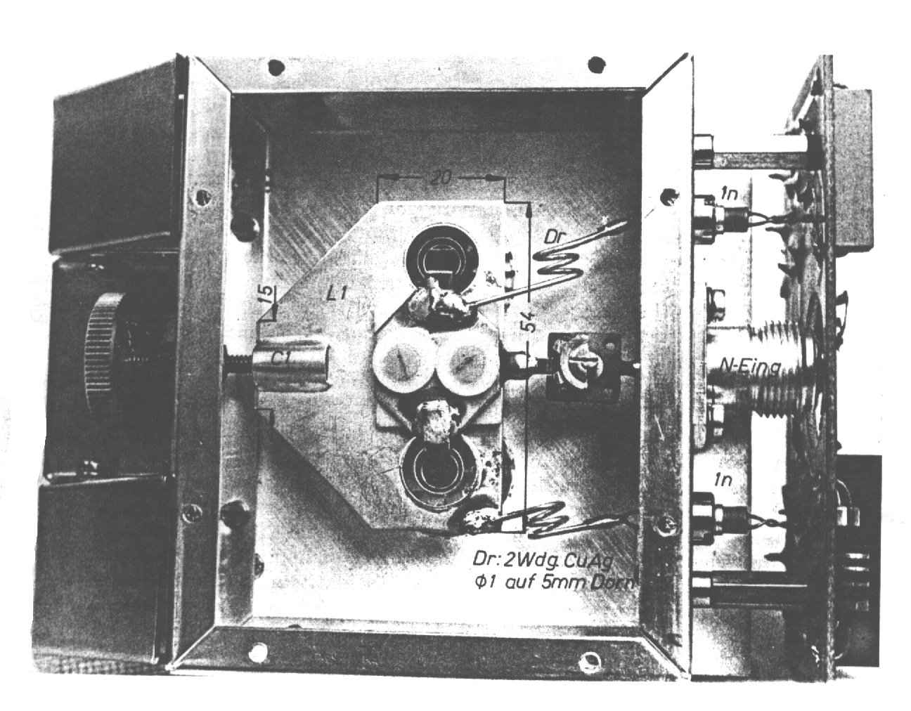
Bild: D: Perspektivansicht
mit abgenommener Luftführungshaube. Der Topfkreisring hat eine Höhe
von 13.6mm und ein Innenmaß von Durchmesser 90mm. Seine Wandstärke
beträgt 5mm. Die acht in seine Wandung oben und unten eingebrachten
M3-Gewinde bieten die Befestigungsmöglichkeit der unteren und oberen
Topfkreisabdeckung mittels M3-Senkkopfschrauben.
E: Perspective view with
the air channel removed. The cavety ring is 13.6mm high and its inside
diameter is 90mm. Its wall is 5mm thick. There are eight M3 threads on
both sides holding the top and bottom plate.
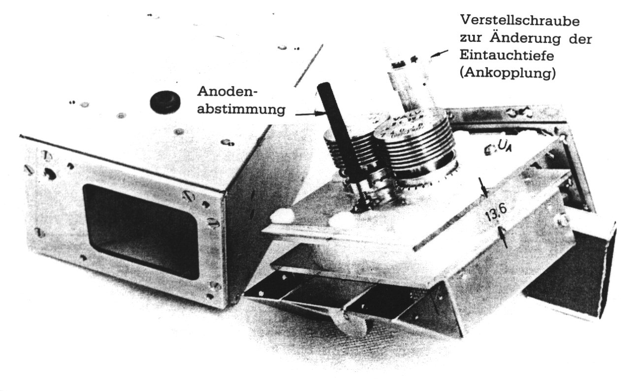
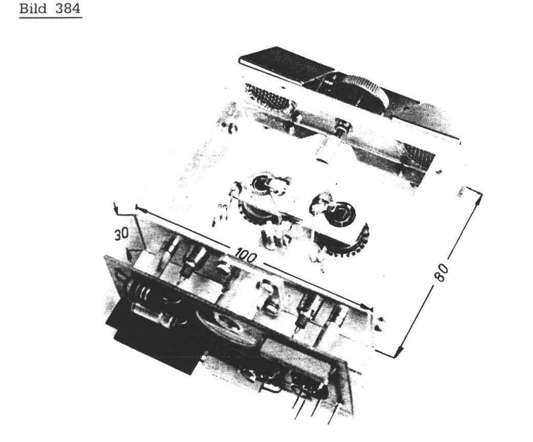
Bild: D: Draufsicht auf
die Endstufe mit Sicht auf die Eingangsbuchse:
E:
Top view of the power amplifer with view to the input connector
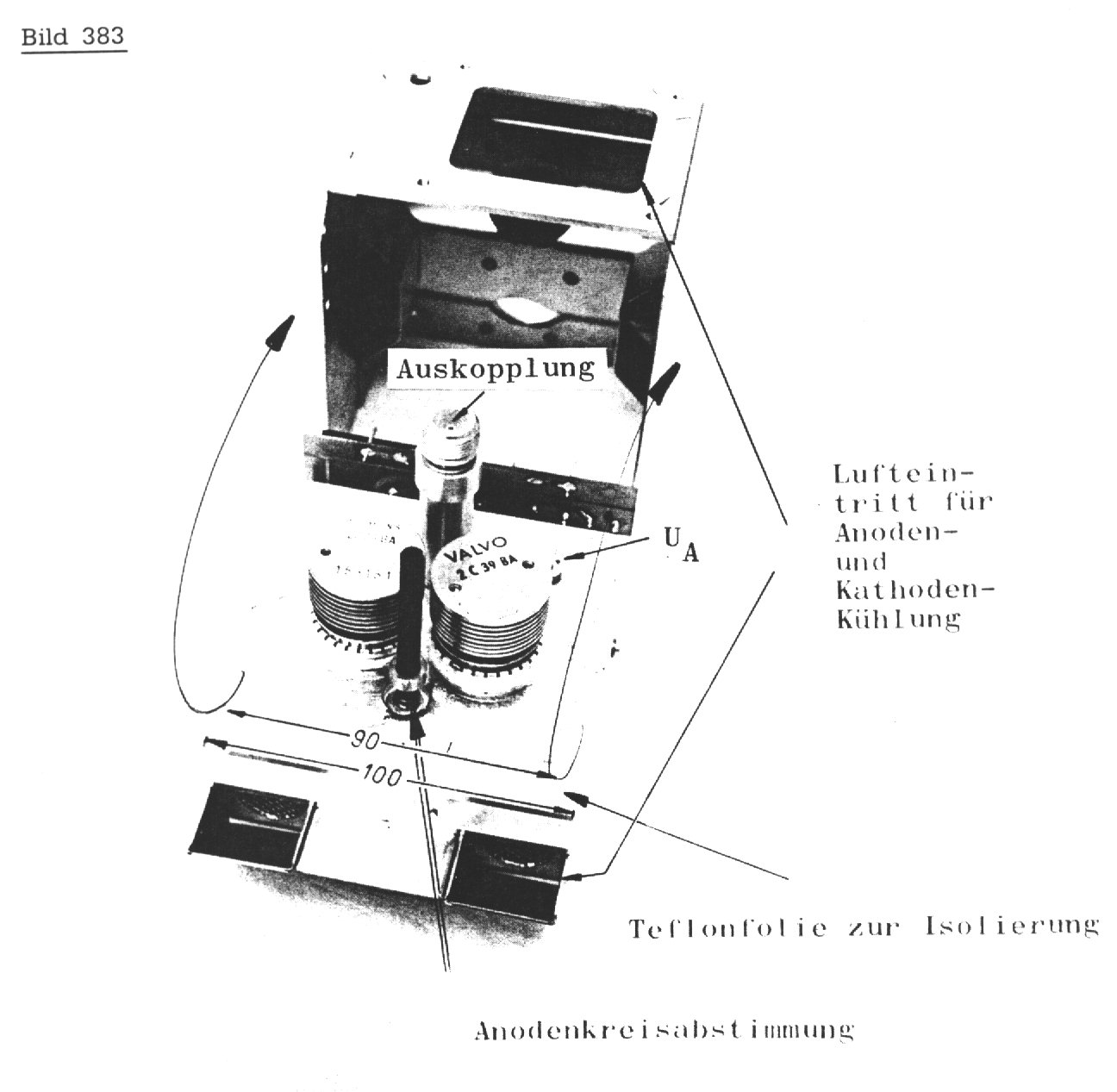
Bild: D: Blick auf den Eingangskreis
E:
View of the input stripline