|
|
|
|
D: Nachdem an meinem Portabel-QTH der nächstgelegenste Digipeater abgeschaltet hat mußte ich QSY machen. Leider fand ich keinen, der mit meinen Behelfsantennen einigermaßen erreichbar war. Immer mangelte es an Sendeleistung. Nach langem Nachdenken über den Kauf eines 35W-Geräts oder einer Endstufe war mir der Preis dafür zu hoch. Die Lösung schien ein Angebot von 70cm-Power-Moduln M67729H2 um ca. DM 30,-/Stück, die zwar nicht direkt für 430-440MHz geeignet waren, aber laut Datenblatt tauglich waren. Gleichzeitig fand ich eine einfache Schaltung um 4 Stück parallel zu betreiben. Also war die Idee geboren. Für ca. DM 200,- entstand eine Endstufe mit 2W Input und 100W Output, womit ich jetzt nach wie vor mein Handfunkgerät verwenden kann.
In den Empfangspfad habe ich einen guten Vorverstärker mit einem MGF1302 eingeschaltet und damit den Empfang meines Handfunkgeräts verbessert.
Natürlich ist diese Art der Verschaltung der Module mit allen Moduln möglich. Ich warte auf den Erfahrungsbericht, der 4 Stück der High-Power-Module für SSB parallelschaltet, mit einem weiteren als Treiber. Herauskomme würde also 5W in und ca. 260W out.
Erklärung der Schaltung:
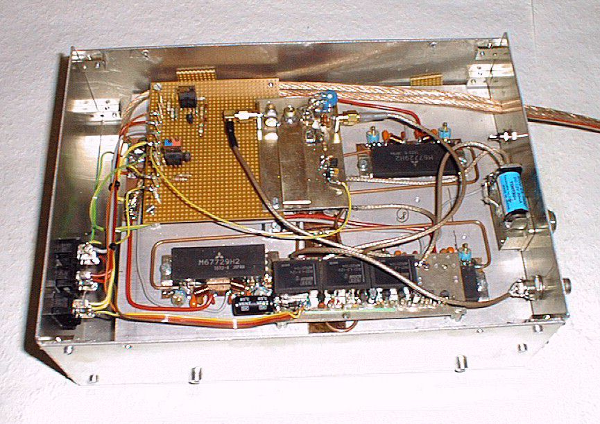
Zwei Leistungsmodule sind parallelgeschaltet. Dort entsteht eine Impedanz von 25 Ohm. Über ein Lambda/4 langes Kabel transformiert sich diese Impedanz auf 100 Ohm. Da davon wieder zwei parallel geschaltet sind, hat man wieder die benötigten 50 Ohm. Ausgangs- und Eingangsseitig wird dieselbe Schaltung angewendet.
Zur Verschaltung verwende ich Semi-Rigid-Kabel. Da ich eine Unmenge mit 2mm Durchmesser hatte, nahm ich davon. Besser ist aber für den Ausgang dickeres Semi-Rigid zu verwenden.
Die T-Verbindungen lassen sich am einfachsten mit Kupferfolie zur Verbindung der Außenleiter machen. Man entmantelt das Semi-Rigid auf ca. 1mm - 1.5mm, verzinnt dann den Mantel, schneidet dann den (hervorgequollenen!!) Isolator ab und lötet die Spitzen zusammen. Dann legt man unter die drei Kabel ein kleines Stück Kupferfolie und lötet die drei Kabelmäntel darauf.
Die Module wurden ebenfalls mit Hilfe von Kupferfolie verschaltet: Benötigt wird pro Modul ein Stück Kupferfolie, das zwischen das Modul und den Kühlkörper gespannt wird. In die Zwischenlagen kommt Wärmeleitpaste. Die Masseanschlüsse des Moduls werden direkt auf die Folie gelötet, ebenso alle Abblockkondensatoren sowie die Enden der beiden Semi-Rigid-Kabel. Die 10pF-Trimmer dienen zum SWR-Abgleich und zum Symmetrieren der Koppler. Die Versorgungsspannung der Moduln wird getrennt nach Treiber und Endstufe verdrahtet, der Treiber geht zur VOX-Auswertung, die Endstufen gehen direkt auf den +15V-Eingang.
Übrigens habe ich die Module verkehrt montiert, bei mir sind auf der Ausgangsseite die langen Semi-Rigid-Kabel zur Zusammenschaltung von jeweils 2 Moduln nötig. Ich rate Nachbauern daher unbedingt darauf zu achten, daß die Ausgangsseiten der Module zueinander liegen kommen.
VORSICHT: Die von mir verwendeten M67729H2-Module haben links den Ausgang und rechts den Eingang. In älteren Mitsubishi-Datenbüchern ist dies verkehrt notiert
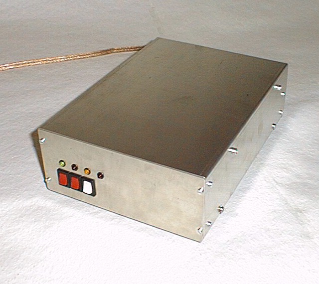
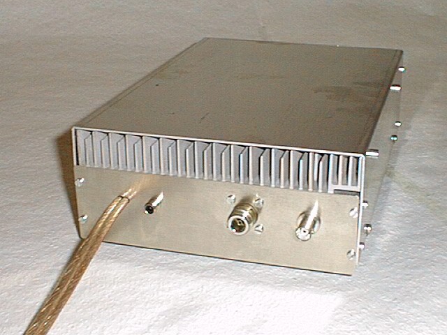
Da ich geschlossene Gehäuse lieber habe als offene Kühlrippen, weil sie sich leichter stapeln lassen, und bei Packet Radio nur eher kurzzeitig gesendet wird, habe ich einen relativ kleinen Kühlkörper verwendet, blase diesen aber über einen temperaturgesteuerten Lüfter an. Weiter sorgt eine Übertemperaturüberwachung auf der VOX-Auswertung "VOX4B" für doppelte Sicherheit.
Technische Daten:
| Input Power
Output Power Verstärkung Power Supply:
Input VSWR |
2W
100W 17dB 15V / 18A
< 1.5 |
siehe auch:
E: Since the closes digipeater at my portable QTH was switched off I had to search for another. I had great troubles to reach these since i can only use simple antennas on the balcony to the backyard there. For every solution there was too less power. After many thoughts to buy a 35W tranceiver or to buy a power amplifier I decided that this is too much money. The solution was found when I saw 70cm power modules M67729H2 for about DEM 30,- each. These were not specified for 430-440MHz but seemd promising according to the datasheet. At the same time I found a solution to run 4 of them in parallel. So this was the final goal. For about DEM 200,- I got a fine PA with 2W input and 100W output, which allows me to continue to use my handy.
To improve the receiver of my handy I added a receive preamp using a MGF1302 into the receive line.
The principles of the parallel connection of these power modules are not limited to the ones I use. I am very awaiting that one who tries to connect 4 pieces of high power modules capable for SSB and a 5th as driver, that would result in a PA with 5W input and app. 260W output.
Circuit Description:
Two power moduls are parallel connected, which results in a 25 Ohms impedance. Using a quarter WL line this impedance is transformed into 100 Ohms. There again two of these are parallel connected and deliver the needed 50 Ohms. There is the same connection at the input and the output.
For the connections I use Semi-Rigid cable (SR). Since I had lots of 2mm diam. cable I took that. But I suggest to use thicker one at the output, since mine becomes a little bit warm.
The T-connections are made with copper foil as connection of the screens. First dismantle the SR for about 1-1.5mm. Then tin the shield and cut the (growing) isolation. After that solder the three inner wires, place a small piece of foil below and solder the SR screens to it.
The modules are also mounted and connected with copper foil. For each module take a piece of copper foil and place it between the module and the heat sink. Between each there is a small amount of heat compound. The ground connections of the module are directly soldered to the foil, also all blocking capacitors and the ends of the SR. The 10pF trimmers are used to align the SWR and to align the coupler. The power supply of the modules is separatly connected for the final and the driver stage. The driver stage's power is supplied by the VOX unit, the final stages's power is connected to the DC input straigt forward.
By the way, I mounted my modules wrong, since I have the long wires on the output side. Take care to have the two short wires which connect two modules together at the output side.
NOTE: The Mitsubishi modules M67729H2 that I used have the output on the left, the input at the right side. There are older datasheets where this is noted wrong.
Since I prefer closed cabinets against open heat sinks because they are easier to staple and since there are only short transmission periods in PR I used only a small heat sink. This is cooled by a temperature controlled blower. Further on there is an overtemperature detection on the VOX decision logic "VOX4B" which can disable all.
Technical Data:
| Input Power
Output Power Verstärkung Power Supply:
Input VSWR |
2W
100W 17dB 15V / 18A
< 1.5 |
see also:
Schematic: (click on the image to view (and save) a high resolution GIF picture)
![[HOME]](green.gif) Last updated 980127 08:00 by DL4MEA
Last updated 980127 08:00 by DL4MEA