Removal / replacement of the dead 'clock backup' coin cell in an Icom IC-7300 and IC-9700
by Wolfgang Buescher, DL4YHF
last updated: November 2023.
Übersetzung in's Deusche (Google Translate, requires Javascript)
Traduction en français
This document describes the removal of the 1 mAh 'clock backup' accumulator
coin cell ("ML414H") in an Icom IC-7300. The web is full of info about this annoying 'feature',
which not only affects the IC-7300, but it will sooner or later haunt
your IC-9700, and maybe similar rigs, too.
The author didn't want to replace the stupid 1 mAh Lithium-Ion cell by another cell of the same type,
only to find it dead a few years later again.
The cell isn't really vital (its death won't affect channel memories and settings), but to the
author, it was annoying to have such a nice radio with a non-functional built-in calendar and clock.
Beware: The original circuit is designed to recharge the orginal accumulator cell, even though very slowly.
Doing this with a primary cell ('Batterie') may be hazardous, causing the electrolyte to leak out and damage nearby components.
1. Removal of the original 1 mAh Lithium-Ion cell (ML414H) in an IC-7300
Remove the IC-7300's bottom-side cover. The culprit sits in a corner of the CPU circuit board,
near the display. There's no need to unplug all those cables, or the board,
or anything in the IC-7300. (Spoiler: In the IC-9700, things are different..)
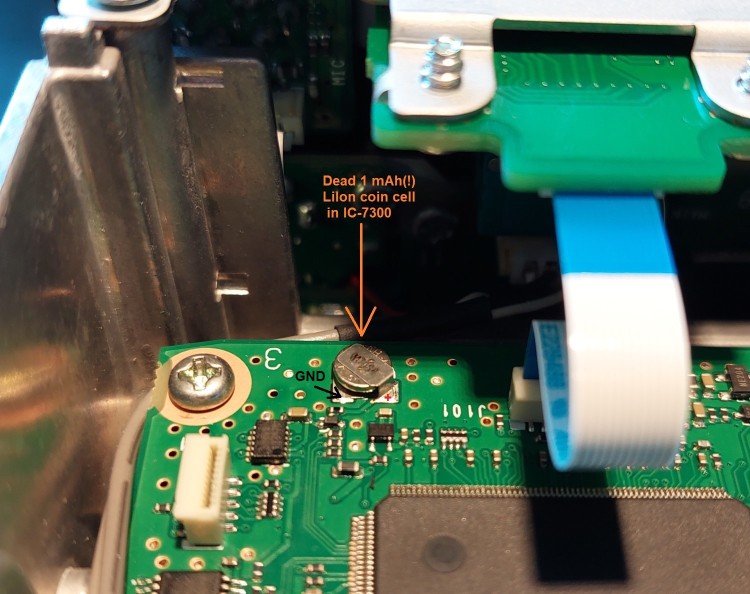
Photo of the culprit - Icom's glorious LiIon coin cell with an incredible
capacity of 1 mAh, shortly before 'brutal removal' as explained below.
If the cell wasn't an SMD part (surface mount), it would be easy to be remove
by simply cutting two wires, or beding it from one side to anoter while heating it
with the soldering iron, and gently pulling it out. No chance here. You need to get
both 'terminals' hot at the same time, and with the tin melted, swipe the cell
off the board - and of course, without flooding everything with a large amount
of molten tin, to let the cell 'swim', hi.
Similar as in other repair cases, a 'component removal tool' was made from
a strip of copper sheet metal (0.5 mm thick), rolled together to form a tube,
with the inner diameter matching the OD of the soldering iron. Then, with a small
cut-off wheel and a motor tool, remote a part of the copper to give the
'Icom Cell Remover' its final, tweezers-like shape (just wide enough for the
to-be-removed coin cell with 5 mm diameter).
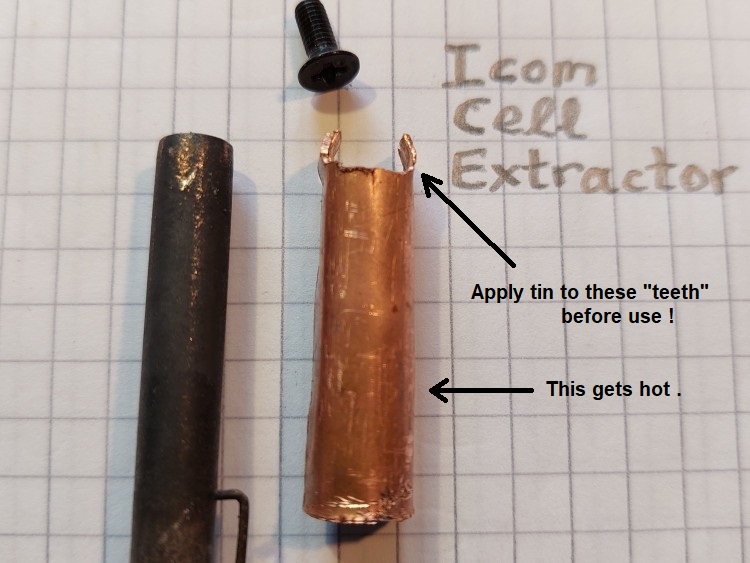
The "Icom Cell Extractor", rolled from copper sheet metal,
to match the diameter of the soldering iron (here: Ersa, shown on the left)
The 'Extractor' tips were tinned in advance to make good thermal contact
with the pads, on both sides of the cell. Then, heated up to 350° C, it was
slipped over the dead cell ("no mercy" - the cell was dead anyway, so fry the
little bastard). After a few seconds, without using any significant
fource, the fried battery could be swiped to the corner of the
CPU board (where fortunately it stopped, after getting in contact with one
of the screws holding the PCB), without ripping off traces:
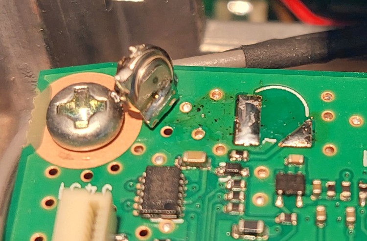
Photo with the dead cell after the 'Cell Extractor' performed its work in an IC-7300.
The 'Extractor' was kept for later, because the cell in the author's
IC-9700 will also die sooner or later ("thanks" to the incredibly large
capacity, and the limited cell lifetime of only of a few hundred
charge / discharge cycles).
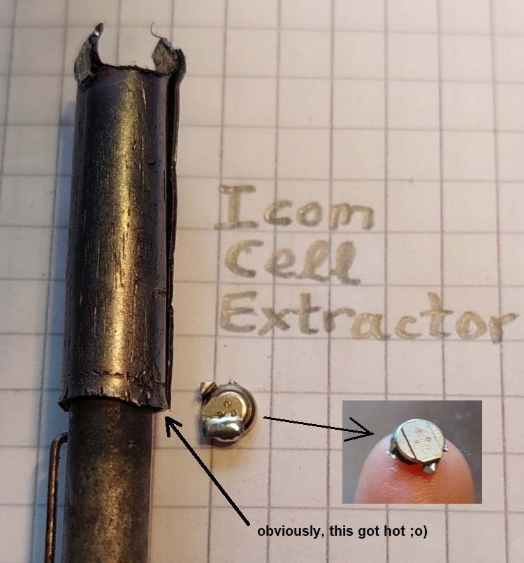
The 'Icom Cell Extractor' and its prey; "grilled and ready for the waste bin".
2. Replacement of the dead cell with two Ultracaps (connected in series for the voltage rating)
Instead of replacing the LiIon rechargable cell with a Lithium battery (which would have
required a diode to protect it from being charged), the LiIon cell was replaced
by two Ultracaps in series, with 5 Farad, 2.7 Volts each.
Use a good brand name (like Maxwell), don't buy crap from you-know-where
with either high leakage current, large production spread, less-than-specified capacity,
high series resistance, or just waste.
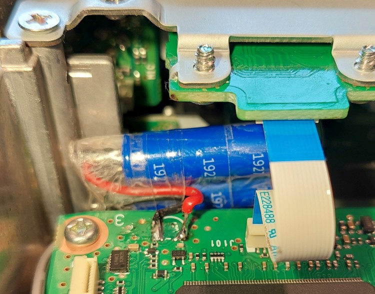
Dead cell replaced with two 'Ultracaps' in series,
IC-7300, wrapped with adhesive tape for safety.
Before installing these capactors in the Icom, they were tested for their
leakage current as described further below. It turned out that the
'guaranteed' maximum leakage specified in the Maxwell "HC Series Ultracapacitors"
datasheet was quite pessimistic - in the fact, the leakage current,
with the charge capacitors stored at room temperature was far less
than specified - in other words: For this purpose, the capacitors were
much better than expected. As already noted in the introduction,
the capacitors were not bought at Ama.., Eba.., Ali.. but at a trustable source.
After slowly charging them to 5 Volts (already connected in series,
with almost perfectly 2.5 Volts per capacitor), and leaving them connected
to the 'charger' for couple of weeks, their internal leakage current
was so low, that the voltage only dropped from 5 to 4 Volts
after several months ! If you're concerned about leakage
current as the author was (before simply trying it), consider this:
In the Icom, the maximum charge voltage is only 3.3 V, thus only 1.6 V
per Ultracap, so the expected leakage current will be even smaller
when used in the Icom.
Note: Before installing the two caps in the radio, make sure that
both caps are equally charged to say 1 Volt per cap. Never exceed
1.6 V per capacitor, or 3.3 V in total !
When pre-charged this way, you don't need to wait for a couple of hours
to let the Icom's original "charger" (3.3 kOhm resistor) charge it.
To check for the Ultracap charging speed, the voltage accoss the caps
was measured during a 10-minute test, with the radio turned on
(or at least connected to an external power supply, which also causes
the weak charging current for the ex-LiIon-cell to flow):
Begin of test: 2.63 V
10 minutes later: 2.66 V
That's a voltage increase of 30 mV in ten minutes, or circa 180 mV per hour.
Ok but not really fast (see next chapter about the modification
of an IC-9700, where the original 3.3 kOhm series resistor was
replaced by 330 Ohm to charge the Ultracaps completely within
two hours).
3. Removal / replacement of the original 1 mAh Lithium-Ion cell (ML414H) in an IC-9700
A few months after the IC-7300's clock battery's demise, the battery in the author's
IC-9700 died, too. Suprisingly, this happened after only one night without
being connected to external DC power. Unfortunately, in the IC-9700, Icom has hidden
the dreadful ML414H (in the IC-9700, component number 'BT251', near 'IC251') under
a large metal "roof" soldered(!) on the 'Main Unit'. The main unit is on the underside
of the transceiver, so you only need to remove the bottom cover to see
the 'Main Unit' - but you still will not see the ML414H cell:
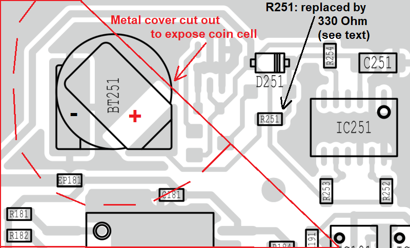
Layout of the IC-9700's main unit, with the dreadful coin cell ('BT251') hidden below
a sheet metal "roof" (edges marked in red, the dashed half circle marks the cut-out area).
An attempt to unsolder the irregular-shaped metal "roof" above the CPU, coin cell,
and many other components failed (too many points that would have to be heated
simultaneously, marked by red arrows in the photo further below). Because the
coin cell is near the edge of the "metal roof", a rounded area just above
the cell was cut away - very ugly, but much easier than a proper removal.
The sheet metal over the coin cell is quite thin, so could be cut from the edge
with sharp scissors, and then 'rolled up' in a half circle
like the lid of a tinned fish can. Then, the cell was unsoldered
as already shown for the IC-7300 further above.
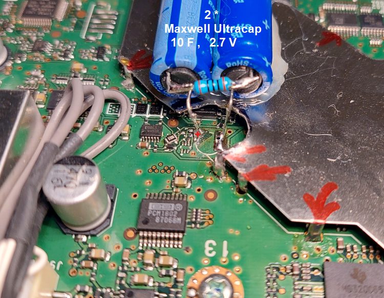
Dead cell replaced by two 'Ultracaps' in series, here in the IC-9700,
glued to the metal shielding ("roof") above the main unit's PCB.
The 100 Ohm resistor visible between the two capacitors
was used to measure the charge- and discharge current.
The two 10-Farad, 2.7 Volt Ultracaps in series (*)
were glued to the sheet metal. For quicker charging, R251 (3.3 kOhm
in the original circit) was replaced by a 330 Ohm SMD resistor. With this resistor,
the initial charge current for a completely discharged Ultracap
would be about 10 mA. After installing the two completely discharged Ultracaps
(for safety), two hours after turning on the IC-9700, the voltage across the caps
reached 2.8 V.
(*) Having run out of 2.7 V / 5 F Ultracaps,
for the IC-9700 repair, easily available 10 F / 2.7 V Ultracaps by Maxwell,
type "BCAP0010 P270 S01", were used. Buy at Mouser or Digikey.)
4. Estimate of the maximum 'clock reserve' after replacing the original ML414H with Ultracaps
From the datasheet of the IC-7300's RTC (Real-Time Clock), type RX-8803LC:
- Minimum clock supply voltage = 1.6 V
- Typical current consumption in 'Backup Mode' = 0.75 uA at Vdd=3 Volt
- Maximum current consumption in 'Backup Mode' = 2.1 uA at Vdd=3 Volt
We're optimitic and assume the "typical" current consumtion (which is justified
because we don't operate the IC-7300 at +85°C in standby, where a semiconductor
like the RTC would draw more leakage current than at room temperature).
With the Ultracaps charged to say 3.2 V (it will never reach 3.3 V due to the
discharge-preventing diode, D381 in the IC-7300, D251 in the IC-9700),
the voltage across the caps may drop by 3.2 V - 1.6 V = 1.6 V before the
clock / calendar stops.
With C = 2.5 Farad (remember, two 5-Farad-Ultracaps in series), that's
T = delta U * C / I = 1.6 V * 2.5 F / 0.75 uA = 5.3*10^6 seconds = 61 days at best.
That's not spectacularly long, but:
Much in contrast to a LiIon cell, which inevitably dies
from a deep discharge, modern Ultracaps tolerate this and don't need to be
replaced every few years.
If you really removed your radio that long from a power supply, it will need
to have the time-and-date set again (or, for the IC-9700, be synchronized
via Internet) - but after leaving the radio connected to DC power for a day,
the clock will be working again for at least a month.
So far, neither the author's modified IC-7300 nor the modified IC-9700
has ever suffered from a lost calendar date/time,
even after being "power-less" for several weeks.
back to DL4YHF's main ham radio homepage