Contents
- Initial QRP tests in spring/summer 2019
- A tiny, light-weight homebrew mesh dish
- The "Oscar-Tröte" (Helix with deep cone reflector for 13 cm)
- More experiments with small antennas for the uplink
- Modified UMTS amplifier with BLF7G22
- Simple homebrew measuring equipment
When Es’hail-2 / AMSAT Phase 4-A / QO-100 was successfully launched
Quatar in early 2019, everyone was in a hurry to get QRV on the new satellite.
So was I, and as a QRP and homebrew enthusiast, the mode of choice
was CW (Morse code). For an initial test, I used a cheap chinese
ADF4351 evaluation board (17 Euros), and a hastily written PIC firmware to program
the frequency, controlled via rotary encoder, and directly drive a
multiplexed 7-segment LED display.
The eval board was mounted on a surplus 10 MHz OCXO, which is almost
as stable as a GPSDO:
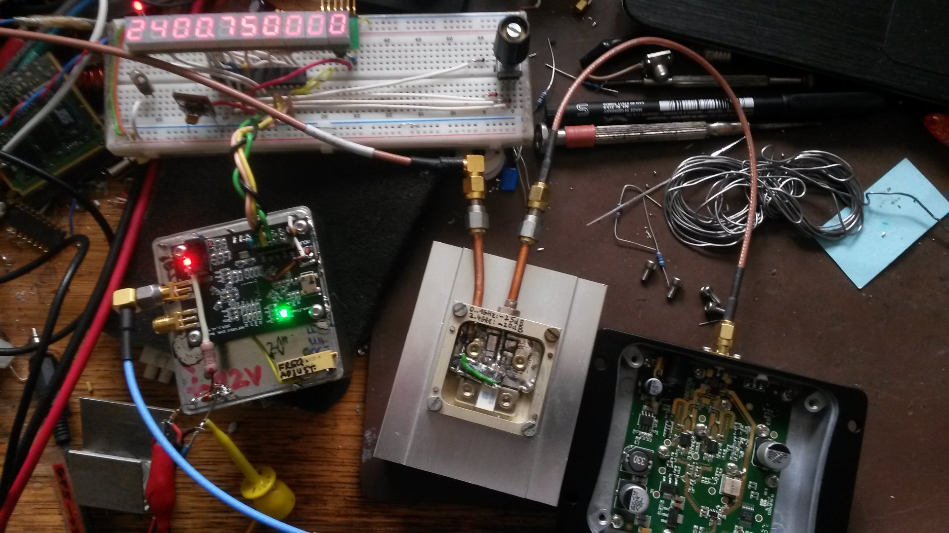
ADF4351 board (left), PIC with display (top), dummyload and amp (right).
Click on the image to magnify.
This kind of worked (with "on-off keying" the driver stage, a SKY65162),
but the loop filter on the ADF4351 was far from being optimal (actually,
what was populated on the board didn't have much in common with the
component values shown in the schematics).
Instead of digging in deeper with the ADF4351, I bought a Taiwanese BU-500
transmit converter (configured for 70 cm IF input) at the Ham Radio fair
in Friedrichshafen, so I was "theoretically" QRV in SSB now, too.
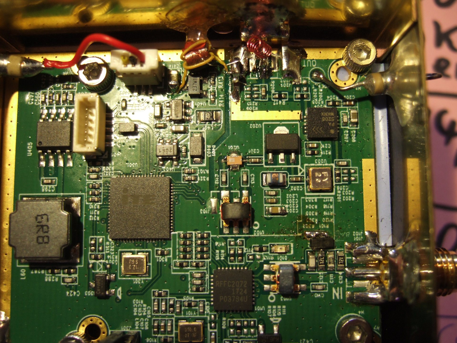
Inside the BU-500 (432 -> 2400 MHz TX converter).
More on the modifications inside this little box further below.
Click on the image to magnify.
The main problem was none of the windows in my flat had a clear view
to the satellite; so the first RX experiments were made outdoors
with the usual satellite TV dishes, a modified PLL LNB, and an SDRplay.
The first successfull QSO was made in CW with a tiny double-quad antenna
held out of the window on a glass-fibre mast (pointing directly towards
the satellite, not illuminating the satellite dish).
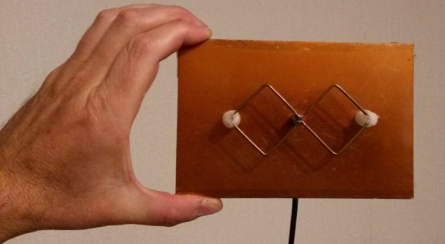
Linear polarized double-quad antenna with copper-clad PCB as reflector
Even with only 1.5 watts into the above antenna (and again, no dish)
from the BU-500 running "barefoot", the signal
was audible, but it didn't attract too much attention when calling CQ.
For a bit more punch, but still QRP (about S7 on the Goonhilly web SDR)
the double-quad was replaced by a 15-turn Helix antenna temporarily
mounted on the opened window. Sure this was an interesting sight
for the neighbours.. but to my suprise, this RHCP Helix was even ok
for a few SSB contacts.
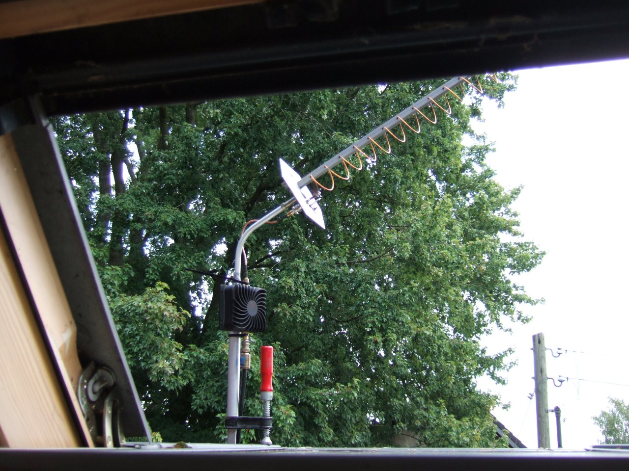
15-turn RHCP Helix tied to the opened window for QO-100 uplink.
Chinese "8 Watt" (in reality less than 4 Watts) 2.4 GHz amplifier just below the antenna.
Click on the image to magnify.
To avoid the cable loss from 7 meters of Aircell 7 (ca. 4 dB on 2.4 GHz)
between the shack and the "antenna window", the BU-500 (in the shack)
now feeds a cheap 'WLAN booster' over the long cable.
With 1 Watt from the TX converter, less than 0.5 Watt arrive at the
input of this amplifier, slightly overdriving it (which is ok for CW,
but not for SSB). With 0.5 Watts on the input (severely overdriving it),
mine delivered 4.5 Watts output at best. I later reduced the drive for SSB.
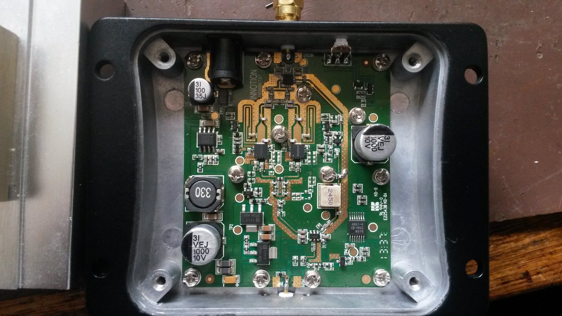
Inner guts of the Chinese "8 Watt" (in reality 4 Watt) 2.4 GHz amplifier.
Click on the image to magnify.
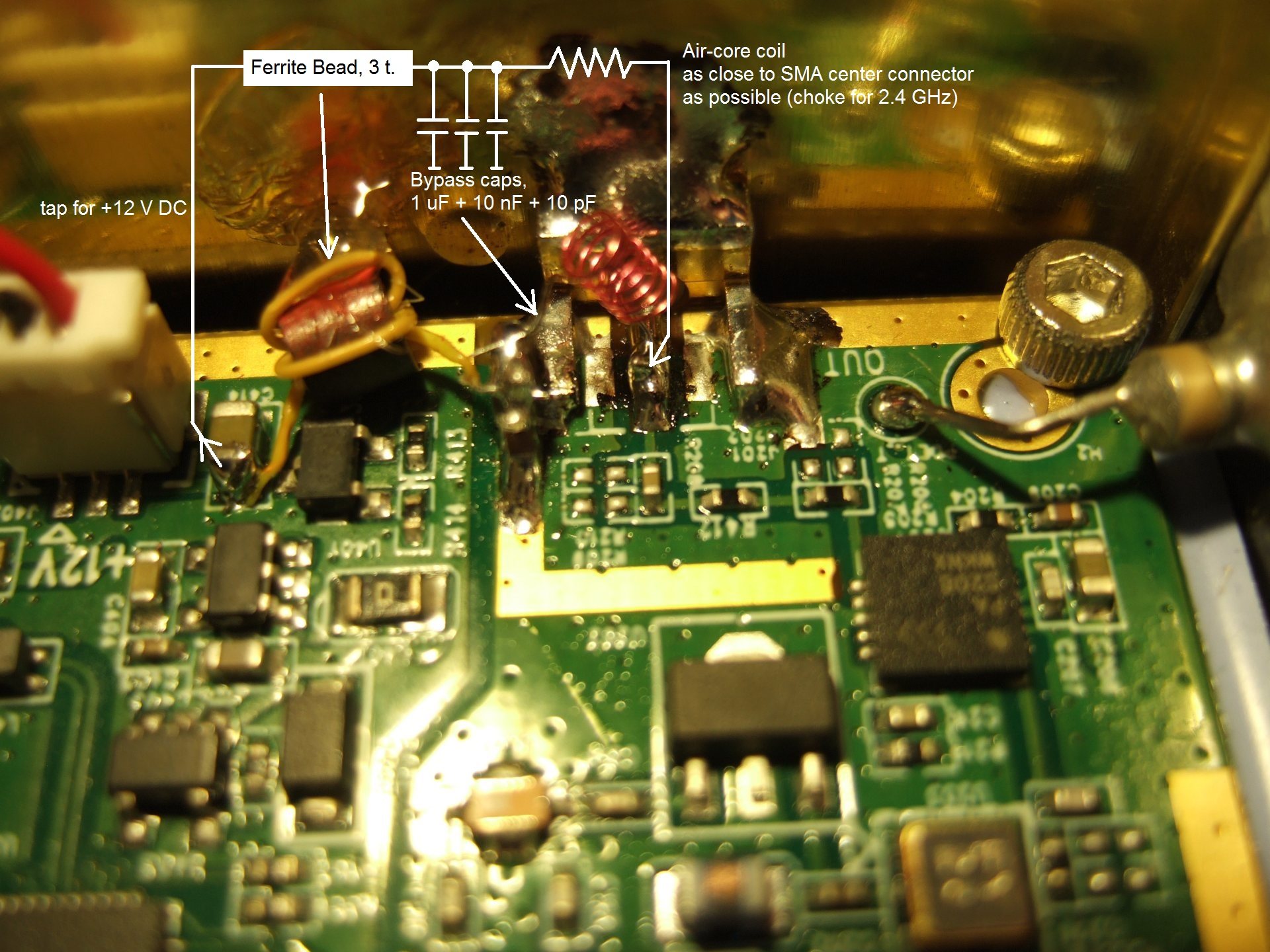
This amplifier was modified for 'permanent transmit' by feeding some
DC into the RF detector (with 10 kOhm from the internal 6 V supply),
and a 'phantom' DC power supply over the coax cable. A similar
'phantom power' injector was also built inside the BU-500, so all
that needs to be connected between TX converter (shack) and the
antenna is the coax cable, which (at the moment) carries the 12 V DC,
and the 2.4 GHz transmit signal.
BU-500 with 12 V DC feed via coax, for the external PA.
Click on the image to magnify.
Maybe in future, the coax between shack and antenna will also
carry a 10 MHz reference for the LNB, and the 739 MHz IF signal from the
LNB to the SDR (or 739 -> 144 MHz converter). Not sure if the
crossover network would still fit inside the PA
enclosure, but the goal is to keep everything as small as possible
for portable operation.
Inside the BU-500 (near the mixer's input), I installed two anti-parallel
Schottky diodes to protect the mixer in case of "operator error"
(i.e. forgetting the 12 dB attenuator between the FT-817 and the 432 MHz
IF input). Under normal conditions, the voltage across these diodes
is way below 400 mV (when they would start to conduct).
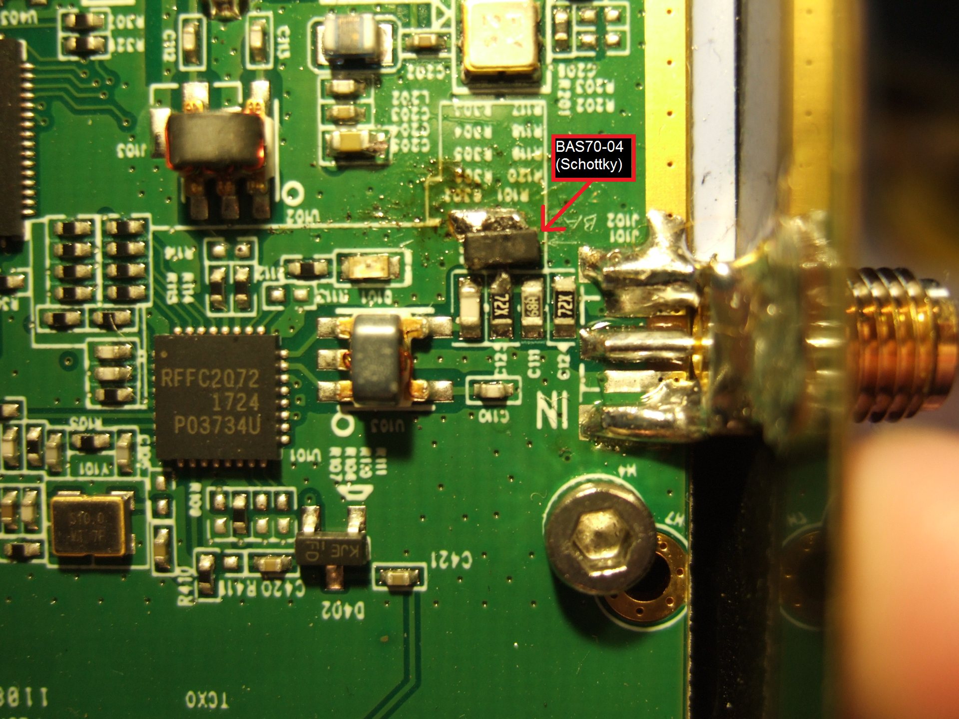
BU-500 with extra mixer protection (BAS70-04, dual Schottky diode).
Click on the image to magnify.
Accidentally transmitting into the BU-500 with 3.5 Watts would instantly
kill the mixer (RFFC2072) as well as the input attenuator (which is
rated for about 200 mW; the absolute maximum rating for the
mixer's input power is +15 dBm, according to the RFFC2072 datasheet).
In July 2019, the "Camping dish" was still only used for reception.
The next step was inspired by the POTY
(Patch Of The Year), but I had problems getting the two dips in the
SWR plot - all I could see on the analyser
was a broad SWR minimum around 2400 MHz, and a narrow dip at 1900 MHz
which was obviously caused by the reflector's resonance.
Also, the RX performance on 10 GHz was at least 3 dB worse than the
original LNB in the focus of the 35-cm "Camping dish". With an 80-cm,
or even a 1-meter dish this would matter too much, but for a small
dish you don't want to lose a single dB of RX sensitivity.
But mounting a larger dish temporarily wasn't an option (to operate
from home), so the story continues...
Because a 13 cm PA module (from Poland) spent several weeks 'in transit'
over Christmas, and the trusty old Helix was a bit weak in SSB
(compared with other users), it was time for yet another antenna
for the uplink, with a bit more gain.
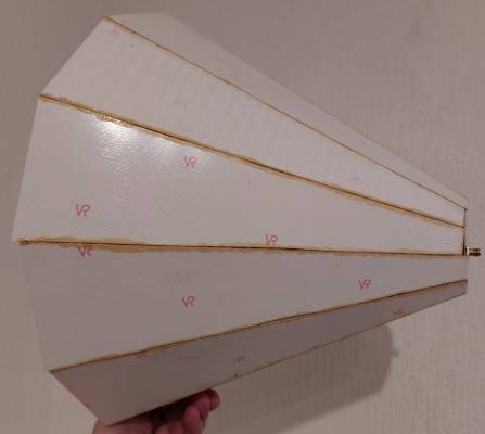
First, a mesh dish was built entirely from parts from the DIY store,
just small enough to be passed through a 60 cm wide attic window.
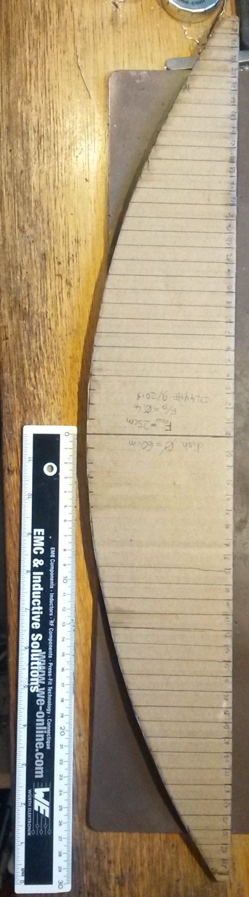
Thus, a template for a 60-cm diameter parabolic prime-focus dish
with 25 cm focal length was drawn on a piece of thick cardboard
(which was then spray-painted to improve stiffness).
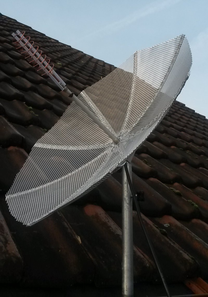
Light-weight mesh antenna, 60 cm diameter with backfire helix feed.
Click on the image to magnify.
Formula for the parabola (snippet from a CalcEd script;
for a given diameter D and focal length F; H = vertical height of the reflector,
all inputs in meters):
D := 0.6       // input: diameter
F := 0.4*D     // input: focal length for given F/D (here: 0.4)
H := D^2/(16*F)
F =:  0.24     // calculated focal length for the given F/D ratio
H =: 0.09375   // calculated height or 'Depth' of the dish in meters
@def y(x)=x^2 / (4*F)  // parabola formula
@plot( X:=0...0.31, y(X) )  // plot HALF of the parabola, X=0=center, mirror the rest
Using the cardboard template, a 'skeleton' was built from widely available
aluminium material, then covered with eight sectors of aluminium 'stretch metal'
(in German: Aluminium-Streckmetall / Streckgitter aus dem Baumarkt).
This 'stretch metal' can be shaped into concave or convex objects,
which is almost impossible with other materials (like perforated sheet metal / "Lochblech").
Since Helix antennas (including helical feeds) are easily fabricated
without precision machinery, the first feed for the dish
(shown above) was a bifillar Helix as described by G8HAJ
(see Helix Feed for 13cm Es'Hail uplink
on Graham's site, but don't miss the important note about the winding sense.
For RHCP after reflection on the dish, the backfire helix
must be wound like a right hand thread).
Here is the double helix used in DL4YHF's light-weight dish:
Double helix for a 13 cm 'deep dish' feed, later protected against rain with thin plastic foil.
Building the antenna was easy, permanent installation impossible. Click on images to magnify.
The double helix was 'threaded' (geschraubt) into two thin
'SMD IC' tubes to hold the turns of the 1.6 mm enamelled
copper wire in place. Details about the balun / impedance
match on the G8HAJ website - see link above.
Because with the feed in place, I couldn't pass the antenna
through the attic window, the quarterwave balun now ends at
a short piece of semi-rigid cable with SMA connector, so
the (fragile) feed can easily be separated from the rest
of the antenna.
On the very first test, the light-weight dish provided about
6 to 8 dB more gain than the
15-turn RHCP helix (see also:
antenna comparisons in a later chapter).
The driving level into the Chinese "8 Watt" WLAN PA could be
reduced to 2 dB below the compression point, which significantly
improved the signal quality, and imho was now acceptable
for rag-chewing in SSB (besides CW).
For such small prime-focus dishes, the "backfire helix" in the
focal point doesn't obstruct as much space as for example
a POTY or a classic Helix with reflector plate would.
If you have a 1.2 meter prime focus dish (or even more),
the area obstructed by the feed is neglectable, but for a
60 cm (or even smaller) prime focus dish, it's not.
So far, I'm very pleased by the performance of this antenna,
and maybe I will build another one that can easily be
disassembled into 4 or 8 parts (segments) for storage
in a suitcase or backpack.
If the "mesh" (expanded metal, Streckgitter) was available
with a smaller mesh size, such an antenna could even work
nicely on 10 GHz for a combined RX/TX antenna.
Performance test on 2.4 GHz, using relative signal levels from the
Goonhilly QO-100 Web SDR
with 2.7 kHz RX bandwidth, USB:
  QO-100 Upper Beacon (PSK), unknown uplink ERP from Bochum: -68 dB
  60 cm Mesh Dish, 2*4 turn backfire helix feed, 3.5 watts : -72 dB
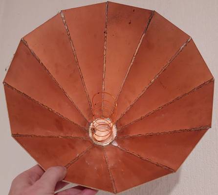
3. The "Oscar-Tröte" (Helix with deep cone reflector for 13 cm)
Don't take this chapter too serious. It's not recommend to build this antenna
unless, like yours sincerely, you have piles of single-sided copper clad PCB
material laying around (thanks Ulli!), a full roll of soldering tin,
and a can of plastic spray to protect the copper from getting stained.
If it doesn't suit your needs as a 2.4 GHz antenna, the reflector (cone)
can be recycled as a decorative lamp by replacing the Helix feed by a light bulb,
and hanging it to the shack's ceiling.
DL4YHF's "Oscar-Tröte" (Helix antenna with deep cone reflector, almost a "horn") ready to "blow",
laid out on a horizontal window pane, for the neighbours to speculate about the purpose. Törööö !
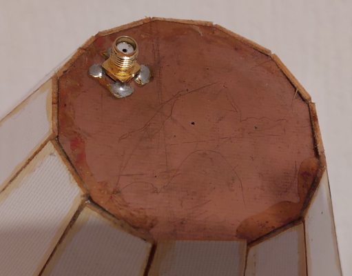
Details of the "horn", from left to right: side view, looking inside at the Helix, and at the base plate
with an SMA connector.
Basically, the "horn" is a RHCP helical antenna with an oversized 'truncated-cone' reflector,
inspired by an article titled "Optimization of Helical Antennas" by
A. R. Djordjevic, D. I. Olcan, University of Belgrade, Serbia;
and A. G. Zajic, M. M. Ilic, Georgia Institute of Technology, Atlanta.
Quoted from their paper (which used to be online as PDF but the original link is broken;
fortunately it was rescued "locally" at datasheets/Antennas/Optimization_of_Helical_Antennas.pdf):
ABSTRACT
Helical antennas have been known for a long time,
but the literature is overwhelmed with controversial
information about their performance. We have
systematically investigated helical antennas located
above an infinite ground plane and obtained design
curves. We have also observed that the shape and size
of the ground conductor have influence on the helical
antenna performance. By optimizing the dimensions of
ground conductors that have the form of a cup and a
cone, we have significantly increased the antenna gain.
Simultaneous optimization of the helix and the ground
conductor is under way to improve the antenna
performance.
(... later, in chapter 3 : )
3. INFLUENCE OF THE REFLECTOR
We have found that the size and shape of the
ground conductor (reflector) of helical antennas have
significant impact on the antenna gain. By shaping the
ground conductor, we increased the gain of a helical
antenna for several dB compared to the case when the
helical antenna is above an infinite ground plane.
We analyzed a helical antenna above an infinite
ground plane, a finite-size square reflector, a cup, and a
cone (Figure 6). (...)
The "Oscar-Tröte" was inspired by the 'Cone with h = 2 * lambda' presented
in the above paper. Parameters: D2 (aperture diameter) = 2.5 * lambda,
D1 (bottom plate diameter) = 0.5 * lambda, Helix length = 2.0 * lambda
(originally same as the height, but squeezing down the helix improved
the gain in the "DL4YHF Oscar-Tröte"). The optimal Helix pitch for this
'unusually deep cone' was 30° (!).
Instead of a circular cone, 12 equally large trapezoidal pieces of PCB
material were soldered together (see photos further above).
Operating QRP with these small antennas in CW (Morse code) on QO-100 was good fun,
because there is no QSB on the satellite, no "big guns" chasing you away
from 'your' frequency because yet another contest is about to start,
there is no 'propagation' suddenly deteriorating during a QSO, etc.
Also, due to the lack of a permanently installed antenna, this fun antenna
was "installed" (i.e. laid onto the window pane) within seconds.
To compare it with other small antennas, I used the Goonhilly Web SDR
(QO-100 narrow band receiver) for relative measurements, and the same
RF power fed into the antenna (about 3 watts after subtracting most
of the cable loss, except for short runs of thin "SMA-SMA" teflon cable):
1.) Linear polarized double-quad antenna (shown in foto further above):
     -90 dB at Goonhilly ("audible but doesn't really attract attention")
2.) 15-turn Helix (also already in use 2019, when it was in a better shape):
     -86 dB at Goonhilly (good for CW QSOs with PY2PIM, IK1FJI, IK2GRA - tnx!)
3.) The "Oscar Tröte" (Helix inside a deep cone reflector, shown above):
     -83 dB at Goonhilly (which is remarkable for the small size of this antenna)
4.) The 60 cm light-weight mesh dish with backfire helix feed (from chapter 2):
     -79 dB at Goonhilly (after more careful alignment than usual..)
5.) The 35 cm diameter "camping dish", fed with "Helix 2.0", horn-LNB inside:
     -82 dB at Goonhilly (not carefully adjusted, more in a later chapter)
4. More experiments with small antennas for the uplink
... to be continued ...
4.1 Camping dish with 'Patch Of The Year
... still under construction (err... I lost the project notes and measurements)
4.2 Camping dish with 'Helix 2.0'
Compared with earlier tests with a 'POTY', and with a 3.5 turn helix to illuminate
this particular dish, the "Helix 2.0" (term coined by Günter, DL6YCL, see
www.qrz.com/db/DL6YCL)
performed suprisingly well (at least a dB better on transmit, in a first very crude
measurement based on the Goonhilly SDR signal strength plot to find the "peak").
... to be completed ...
5. Modified UMTS amplifier with BLF7G22
Here only in short form ... details and measurements stored on the author's local harddisk,
Elektronik_Projekte/2.4GHz_Transmitter_QO100/13cm_40Watt_PA/13cm_UMTS_PA_mods.htm .
Unfortunately this power amplifier module (only the populated PCB with two transistors,
but without heatsink, sold for about 35 Euros in 2019 or 2020) seems to be not available
anymore. Thus this chapter is mostly of 'historic interest'. See also:
forum.amsat-dl.org/index.php?thread/2906-2-4-ghz-pa-from-bisonelectronics/ .
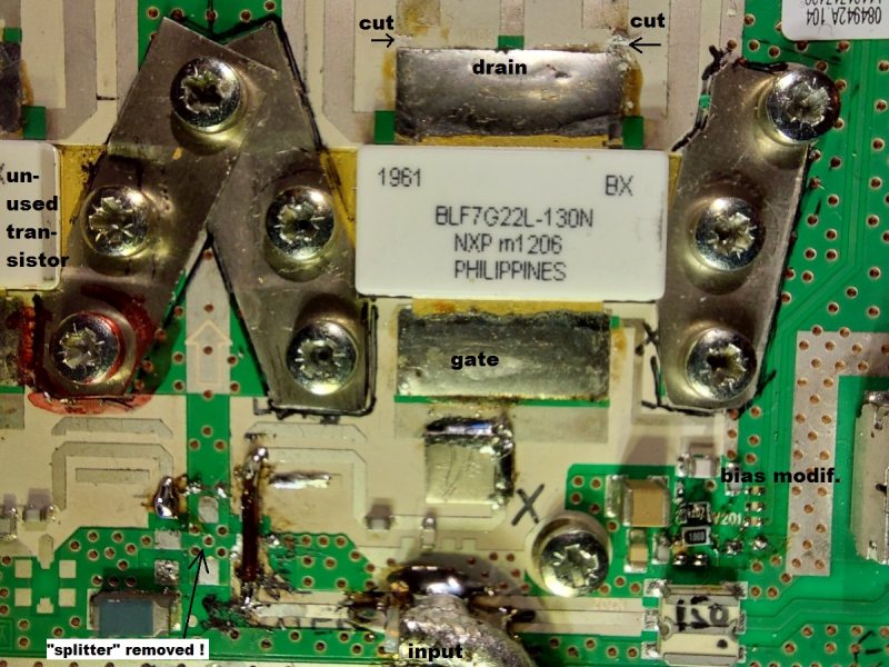
Closeup of the modified (Nokia?) UMTS power amplifier,
originally operated on 2110 .. 2170 MHz with 2 * BLF7G22L-130N
in 'Doherty' configuration. For the narrowband transponder,
only ONE of the transistors (the right-hand one) is in service.
After some tweaking, including the removal of the 90° input splitter,
and completely disconnecting the unused transistor from both
input (gate side) and output (drain side), a gain of 15 .. 16 dB
at an output power in excess of 30 Watts could be obtained.
Measurements when operating at 24 Volt DC supply (not 28 Volt):
     IC705P |  P_in   | P_out  |  G
   ---------+---------+--------+------
     "1 %"  |   27 mW |  0.7 W | 14.1 dB
     "2 %"  |   46 mW |  1.4 W | 14.8 dB
     "5 %"  |  126 mW |  3.7 W | 14.7 dB
     "10 %" |  245 mW |  7.1 W | 14.6 dB
     "20 %" |  417 mW | 13.2 W | 15.0 dB
     "40 %" |  832 mW | 23.4 W | 14.5 dB
     "50 %" | 1047 mW | 26.3 W | 14.0 dB

    IC705P = "RF Power" setting in the IC-705.
              This is not the power fed into the BU-500 !
              There was an 12 dB attenuator, and several meters
              of RG-58 cable between IC-705 and the upconverter.
    P_in  = input power to the modified UMTS amplifier,
              delivered by the BU-500 on 2.4 GHz.
    P_out = output power, delivered by a single BLF7G22L-130N
              when supplies with 24 V DC .
Conclusion: Very moderate "compression" at the 25 Watt output level,
which by the way is better than seen from many "linear" amplifiers
for VHF, when operated slightly below the upper power limit.
More than enough power even for the narrow band transponder,
even with the toy antennas for portable operation shown on this page.
Besides the OCXO-driven ADF4351 synthesizer shown in the introduction,
not much equipment is really necessary. What you will need is
a directional coupler suitable for 2.4 GHz (available for a few Euros,
see discussion on the AMSAT-DL forum; this is also shown in the description
of the El-Cheapo "VHF / UHF diode power meter", which doesn't require much more
than an SMA jack, two 100 Ohm SMD resistors, a microwave Schottky rectifier diode,
and a standard digital multimeter with 0.1 mV resolution in the 200 mV display range.
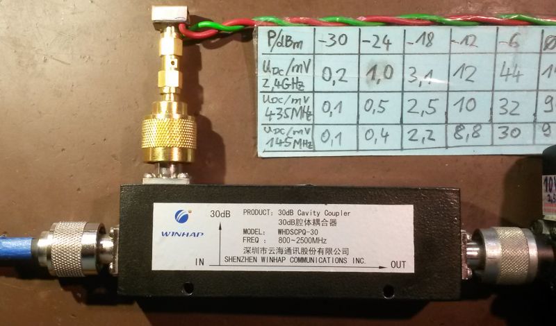
Diode power meter connected to a Chinese directional 'cavity' coupler.
TX output on the left ("IN"), forward power attenuated by 30 dB on top connector.
To measure the reflected power, reverse "IN" and "OUT" port.
Details about the diode power meter are in an separate
documet (follow this link), since it's not especially for QO-100.
In fact, the diode power meter also works well on VHF, and can be used
for "QRO" (high power) when attached to a suitable directional coupler.
As more compact 'power monitor' with direct readout for forward an reflected
power, an old (and for UHF, unusable) N connector "angle adapter" was cut
into two halves with a hacksaw, then "re-arranged" with a piece of brass
sheet metal as measurement chamber. Two small strips of double-sided,
copper-clad PCB material were added to the cavity later (not visible in
the photo below). The prototype is just too ugly inside but it works
very well: 52 Ohms input impedance when terminated with a "good" 50 Ohm
dummyload on 2.4 GHz. After optimising the SMD termination resistors
for the two coupling lines, the directivity exceeded my expectations,
and so the "double power meter" now remains permanently in the setup.
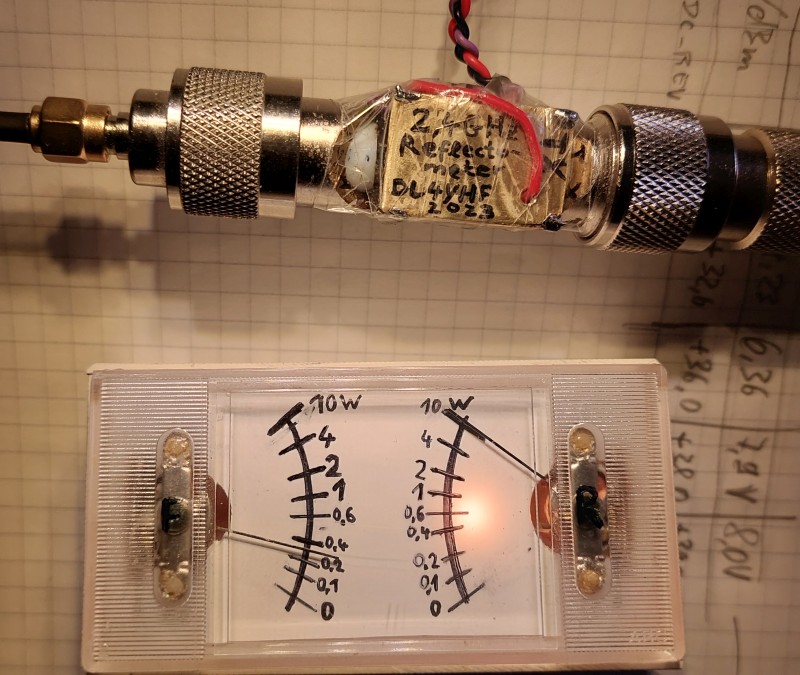
Homemade 2.4 GHz 'SWR meter' (actually two power meters for reflected and forward power)
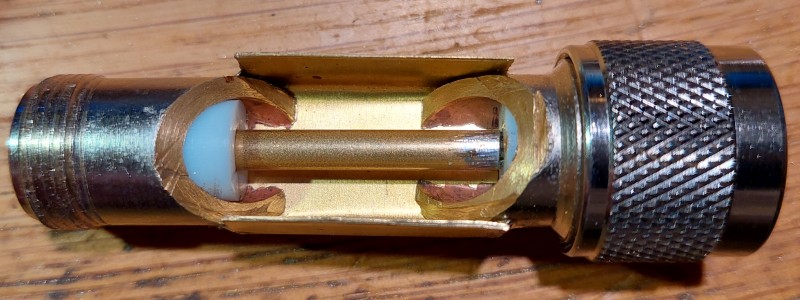
50 Ohm "Cavity" for the reflectometer between the two halves of
what used to be a cheap N-connector angle adapter before.
To achieve a sufficient 'dynamic range' for the display, the forward-
and reverse voltages (rectified by BAT62-02V diodes inside the "Cavity")
pass trough passive, non-linear networks that attenuates high voltages
more than low voltages. Thus the 0 to 600 mW range occupies the lower half
of the meter's angle, while 0.6 to 10 Watts occupies the upper (see
photo of the meter "in action").
Actually, the "non-linear element" is a white LED under each needle instrument,
which begins to conduct (and light up !) around 3 Volts from the RF rectifier.
As a nice by-product, the scale illuminates itself if the RF power exceeds 0.6 Watts.
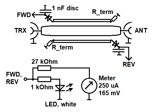
Circuit diagram of the 13 cm Reflectometer.
Lower part duplicated for the "FORWARD" and "REVERSE" branch.
|