Remote CW Keyer
by DL4YHF, 2026-05-14
Contents
- Introduction, translations, download link, user's group
- Keyer Application (for a windows PC)
- Main menu, status line with indicators, tabsheets
- I/O- and Rig Control configuration
- 'I/O' tab (COM ports and I/O signal selection)
- 'Rig Control' tab
- Rig Control Method / Protocol
- Hamlib server
- Additional COM Ports
- Winkeyer emulation, Winkeyer host
- Serial Port Tunnels (e.g. between client and server)
- Virtual Rig Ports (emulate 'their own radio' for 3rd party applications)
- Serial Text Terminal
- Detailed Settings (dialog for additional COM ports)
- Configuring com0com (Virtual Null-Modem) as bridge to other applications
- Keyer Settings tab
- 'Basic' keyer settings (always available / usable)
- 'More' keyer settings (for Winkeyer or DL4YHF's USB CW Keying Adapter)
- Audio Settings
- CW Sidetone (overview and multiple ways to generate it)
- Network Settings and Client/Server operation
- Network Functionality
- Allow access through the 'Windows Defender Firewall'
- Operation as Server
- Operation as Client
- Network Status
- Accepted Users and Permissions
- Built-in HTTP Server and the 'Admin Password'
- Client/Server test in the local network (step-by-step run-through)
- Debug tab / Error History / Parameter List
- Context Menu for the 'Debug' tab / error history
- List / Edit Rig Parameters on the Debug tab
- Live display of 'Rig Control' traffic on the debug tab
- Test tab
- The 'Timing Scope'
- Timing Scope Trigger
- Interactive Readout / Timing Measurements
- Sources selectable for the scope's 'Channel 4'
- The 'TRX' Tab (Transceiver Control with spectrum display)
- VFO Frequency Control
- Transceiver Mode Control (CW,USB,LSB,FM,..)
- Band selection and 'Band Stacking Registers'
- User defined bands and frequencies (in RCWKeyer_Bands.txt)
- Spectrum Reference Level and other spectrum/spectrogram related controls
- Spectrum Span (displayed frequency range)
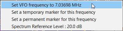
- Frequency Markers, Frequency Info, Beacon Display
- Chatbox to exchange short text messages between sysop and users
- The 'Memory' Tab (with transmit memories and macros)
- Built-in Morse Decoder
- Morse Decoder Output Format
- Decoding CW from the received audio signal
- Installation / Deinstallation, etc
- Installation
- Deinstallation
- Location of the configuration files
- Automatically running the 'Remote CW Keyer' when starting windows
- Technical Details, Functional Descriptions, Circuit Diagrams
- Methods for remotely keying modern radios
- Keying via Ci-V
- Keying via USB / Virtual Serial Port
- 'Audio' keying
- Keying the 'old fashioned way' via the rig's Morse key input
- Connecting the Morse key contact(s) on the 'client' side
- Polling the Morse key via serial port
- Generating the Morse 'sidetone'
- Sidetone generated by the keyer's microcontroller
- Sidetone from the serial port's data output (TXD)
- Low latency audio output from Windows 10 / 11 ?
- Network functionality details and troubleshooting
- Network Error Messages (on the 'Debug' tab)
- Network troubleshooting
- Audio sample format for 'streaming' over the network
- Low-bandwidth 'CW keying' format for the network
- Circuit Diagrams
- Simple Paddle Adapter with sidetone output for the serial port ('client' side)
- RF Sniffer (for a radio / PA keying test with the Timing Scope)
- Simple Keying Adapter for the serial port ('remote radio' side)
- Command Interpreter for 'programmable functions'
- Tokens to control I/O Ports
1. Introduction
Remote CW Keyer started as an experiment to transceivers 'remotely'
to send Morse code ("CW"), not by entering text on a keyboard
(that modern Icom rigs can translate into Morse code), but by
connecting a real Morse key (straight key, elbug, paddle)
to the PC on the client side.
The only required hardware is a Windows PC (or Linux/WINE?),
a serial port or off-the-shelf USB to RS-232 adapter,
and a simple homebrew adapter shown later in this document.
The timing is accurate even at speeds way above 25 WPM,
with a very low sidetone latency when tapped from
the serial port's TXD output (abused as an 'audio tone generator').
A simple TCP client/server was added to allow remote keying via internet,
the transfer of audio from server to clients, and (for modern Icom rigs)
a remote VFO control with spectrum / spectrogram display. The same TCP/IP connection
can also be used to 'tunnel' data from third party applications (like Loggers,
and even WFView) to the radio, as if they controlled the radio directly.
For a start, read these chapters from top to bottom, and try not to be distracted
by the many links in this document - they are intended for
experienced users, to navigate through the document quickly.
To simply use the Remote CW Keyer which someone else has already configured,
skip all the chapters about configuration/setup, and begin with the TRX tab,
because that's what you will use most of the time (especially if the Remote CW Keyer
controls a 'modern' Icom radio).
Current state of development and revision history:
- 2025-07-12 :
- Added Virtual Rig Ports (to emulate 'their own radios'
for 3rd party applications), similar as Serial Port Tunnels,
but a virtual rig port allows both (the 3rd party app and RCW Keyer)
to actively control the radio. A virtual rig port
can even emulate a different radio than the one actually connected.
- 2025-06-07 :
- Added the Additional COM Ports,
with configurable purposes like a 'Winkeyer Emulator'
for an easier interface with external logging software
like N1MM Logger+ . Traffic to/from these ports can also pass
through serial port tunnels between client and server,
without being modified, to remotely control equipment (instead of just 'keying' the rig in CW).
- 2025-04-20 :
- Added the Audio-CW-Decoder,
but so far that doesn't cope well with rapid amplitude changes
caused by QSB, and the receiver's automatic gain control.
Especially when the radio's IF filter (or DSP filter) is 'very narrow',
the FFT-based tone decoder fails to measure the
Signal-to-Signal-plus-Noise ratio.
More interesting than the CW decoder itself: Plotting the
audio spectrum (byproduct of the decoder's FFT) in the
timing scope, and watching
people stomping on each other in a CW pileup.
- 2024-11-20 :
- Replaced the zipped archive by an Inno Setup based installer,
since at least one user found it too difficult to extract the
entire content of a zipped archive (including sub-folder and
their files) into the recommended destination folder,
when downloaded from a web browser.
For details on how to use the installer (Remote_CW_Keyer_Setup.exe),
see Installation (in a later chapter
of this document).
- 2024-06-16 :
- Integrated spectrum / spectrogram display with VFO- and mode control
on the TRX tab.
+ Provisions to translate the GUI into other languages
(see sources/Translations.c, contained in the zip file).
+ Translation into Dutch language by PD4DA. Thanks Dimitri !
- 2024-05-12 :
- Added a 'Straight Key' morse decoder, to check the CW signal on the server side
at speeds exceeding the the author's 'by-ear' decoding capabilities.
+ Increased the size of the Morse-keying RX FIFO, to make keying over a
TCP/IP network more robust.
+ Added a manual setting for the network latency in the main menu.
- 2024-01-19 :
- Rudimentary Network capabilities (TCP client/server), including low-bandwidth
audio streaming from server (with the "remote radio") and client ("operator").
- 2023-11-19 :
- Initial proof of concept: Elbug emulator running on a Windows PC
with paddle inputs on RS-232 modem status lines, and CW keying output
on RS-232 'DTR'.
-
- Note for German users / Hinweis für deutschsprachige Anwender:
- Am Anfang der Entwicklung war dieses Programm nur eine Machbarkeitsstudie
für die Integration eines echten CW-Keyers (keine Texteingabe) in wfview.
Da sich die Integration in wfview als zu
aufwändig herausstellte, wird der 'Remote CW Keyer' als
eigenständige Windows-Applikation weiterentwickelt.
Ein deutschsprachiges Handbuch existiert bislang noch nicht,
die Benutzeroberfläche kann mittlerweile aber von Englisch
auf Deutsch umgeschaltet werden (im Menü 'Settings' .. 'Language / Sprache').
Als Ersatz für ein Anwender-Handbuch in deutscher Sprache kann bis
zur Vollendung der Dokumentation die Übersetzung per 'Google Translate' dienen:
Remote_CW_Keyer.htm per Google in's Deutsche übersetzen.
Die Übersetzung funktioniert nur online im Browser mit aktiviertem Javascript.
Das Resultat ist teilweise noch etwas drollig, aber durchaus brauchbar.
- For other languages, try these links to 'Google Translate':
-
Une traduction française est disponible ici.
Una traducción al español está disponible aquí.
Una traduzione in italiano è disponibile qui.
Een vertaling in het Nederlands is hier beschikbaar.
Or
select any other language on 'Google Translate' yourself (enable Javascript, then select your language).
Download (link)
A self-unpacking installer for Windows is available on the author's website:
www.qsl.net/dl4yhf/Remote_CW_Keyer/Remote_CW_Keyer_Setup.exe.
Details about how to use the 'Inno-Setup'-based installer follow in a
later chapter (please read it if you are not familiar with
installers, and a paranoid operating system that will prompt you with a warning
about installing an 'unrecognized app', etc).
The installer does not contain C sources. Only for the curious, the sources are in a separate file:
www.qsl.net/dl4yhf/Remote_CW_Keyer/Remote_CW_Keyer_Sources.zip.
You don't need the sources to use the software. In fact, you would need a rather old Borland C++ Builder
to build the application yourself.
User's Group
For a limited time (using the 'free' features at groups.io for a maximum number of 100 users),
there is a User's group at https://groups.io/g/RemoteCWKeyer-Users.
Only members can post to the group, but messages can be read by anyone, so you don't need
to become a member to look for info (hoping that the 100-member-limit for the 'free' group
at groups.io will be sufficient, until the program reaches a mature state).
2. Keyer Application (for a windows PC)
At the moment (2024-06), the 'Remote CW Keyer' application still lacks
a shiny skin (considered not-so-important by its developer),
but it's good for fun, but works locally as well as via local- or wide area
network (TCP/IP), and can even be used to improving CW skills,
especially the timing.
It requires a Morse key (straight key or 'paddles') connected to
a 'Windows'-PC, with an off-the-shelf USB <-> RS-232 adapter,
and a few passive components in between. No need for a special
hardware / electronics / ASIC / microcontroller (at least not for a start).
For truly remote operation, the CW modulation, the received audio,
control and status information, and (for modern Icom radios) even the rig's spectrum display / waterfall is transferred
through the same TCP/IP connection. Depending on the internet connection's bandwidth,
the Server may even service multiple clients at once.
The keyer application automatically passes the key from one client to the next
(if anyone 'takes it') when the configurable TX hang time expires.
2.1 Main menu, status line, tabsheets
The upper part of the Remote CW Keyer's main window shows..
- The program's title ('Remote CW Keyer'), followed by the instance number
in square brackets. There may be multiple instances running on the same machine,
with different configurations. '[1]' is the first running instance,
'[2]' would be the second, etc.
- Additional info like '(Server)' or '(Client)', depending on this instance's
Network configuration.
- A screen-space-saving main menu (no icons, no ribbon, no whistles and bells)
- An always-visible status line,
with 'On Air' status indicator,
an input field for commands or text to be sent (without a Morse key, oh dear),
and the current date and time in UTC,
- A couple of tabsheets to switch between the different
'views' of the main window (config, keyer, audio, remote TRX control).
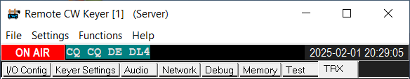
Screenshot of the Remote CW Keyer's main window, upper part,
with title bar, main menu, status line,
and various tabsheets.
2.1.1 Items in the main menu
Most items in the main menu should speak for themselves.. but anyway, here is the nested structure:
2.1.2 Status line with 'On Air' indicator, command / TX data input, and date / time display
The status line contains three fields: the status indicator itself, an input field (single-line text editor) for commands
or text to be sent, and a date / time display in UTC (ISO-8601 format: YYYY-MM-DD hh:mm:ss).
2.1.2.1 'On Air' status indicator
The Status Indicator ( = the leftmost panel in the status line) may show...
- [ off ]
- Neither keyer nor remote control are running, most likely because
it requires input on the I/O configuration tab (select COM ports,
radio model, keyer type, etc).
- [ idle ]
- No active keying; the radio is currently in RECEIVE mode.
- [ ON AIR ]
- The radio is currently transmitting, the "PTT" (Push-To-Transmit) output is active.
Text sent with a real Morse key is displayed in the field right next to the status indicator,
using the morse decoder's output format.
- [ TX MEM #.. ]
- Currently sending text from one of of the CW memories (not from the Morse key).
The digit after the '#' is the memory number, 1 to 6.
- [ TX Text ]
- Currently sending the text from the edit field right next to the status indicator.
More about this 'direct text input' (aka type-ahead buffer) follows
in a later chapter.
If you prefer 'real CW', sent directly with an elbug or straight key,
just don't enter anything in the input field on the status line.
- [ OnAir,SIM ]
- The radio would be transmitting, but it isn't,
even though the "PTT" (Push-To-Transmit) input is active (asserted).
This happens when the manual PTT switching input
has been configured and is currently active (e.g. "microphone PTT switch pressed"),
but the option ☑ Disable Transmission has been
checked on the Keyer Settings tab (or in the
main menu under 'Settings') to avoid going 'on air' while practicing CW with the local
sidetone output.
- [ Off-air CW ]
- This state can only occur when the keyer is configured for
manual PTT control, but the key (or memory keyer)
is operated and currently 'generates CW' that is not transmitted ON-AIR,
but only sent through the local sidetone output.
If this is bugging you, set the 'Manual PTT switching input' to 'NONE'
on the keyer's I/O configuration tab. Then, the transmitter goes
'On Air' without a manually operated PTT.
- [ paused ]
- Transmission has been paused by pressing the 'panic button' (ESCAPE key).
Click on the indicator ("[ paused ]") to un-pause it again, and resume normal operation.
The center part of the status line is a single-line input-
and display field for multiple purposes. Actually, it's a 'Rich Text' edit
control for individually coloured characters.
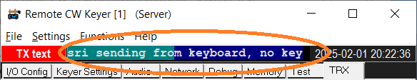
Command- and data input field in the keyer's status line,
while sending text from the PC keyboard:
Green = already sent,
Blue = typed into the editor but not sent yet
In the current Remote CW Keyer version, the command / data input field may...
- show characters sent from the operator's own elbug or straight key
(the preferred method of sending in 'real QSO mode').
- show characters sent from any of the six keyer memories.
(characters are appended to the edit field in the moment they are being sent by the CW generator).
- show characters sent by another user, or decoded from the received audio stream (experimental feature).
- show characters entered via the PC's keyboard, using different colour for characters
typed in but not sent yet, and characters already sent
(see next chapter).
- be used to enter commands for radio- or even rotor control (commands begin with a '#' character
to tell them from text to send in Morse code.. more later)
2.1.2.3 Sending text without a Morse key, from the input field in the status line
Even though sending text with a real Morse key
(keyer, paddle) is more fun in a real QSO than input via a keyboard,
text for transmission can also be typed into this input field. It then acts like a type-ahead
buffer. Depending on your typing speed (on the PC's keyboard), and on the CW speed, you start typing the first few characters before actually beginning to send.
Then, when it's your turn to send, press the ENTER key (aka 'Return') while the keyboard
focus ("blinking text cursor") is still in the
command- and data input field.
As the CW Generator sends characters in Morse code, they will turn green in the edit field.
Characters not sent yet remain blue, until the CW generator catches up.
If the generator has nothing more to send, you have got a few seconds
to think about what else to send; otherwise (without more
characters typed into the edit field) the CW keyer / generator will stop
transmitting, and switch back to reception shortly after the text has been sent
completely.
- Note:
- This time before automatically switching back to receive
does not depend on the keyer's TX delay time,
the TX hang time, or the
'stuck paddle' watchdog.
Similar as when sending text from one of the six keyer memories,
a transmission from the edit field (as "type-ahead buffer") can be stopped at any time
by pressing F12.
Example (sending text typed into the input field in the status line):
- While the status indicator still shows 'Idle'
(not transmitting), text can already be typed in.
Set the keyboard focus to the input field, and press the first character
to send. If the old content of the field wasn't a "text for transmission"
(but e.g. an info from the system, or a text sent to you by the server's sysop),
the field will be automatically cleared when entering the first character:
[ idle ]q
- Type more characters to send into the edit field, still in receive mode (idle)..
[ idle ]qrl ?
- Press ENTER (aka 'Return') to start transmitting..
[TX text ]qrl ?
- Wait for the end of transmission .. or keep on typing while transmitting..
[TX text ]qrl ?
- Even when there's no more text to send, the program remains 'On Air' for a few seconds:
[ ON AIR ]qrl ?
- Without more characters typed into the input field, the program switches back to receive:
[ idle ]qrl ?
- The 'alreay sent' characters remain in the edit field. So you can send the same string again by pressing ENTER,
or edit it (using the cursor keys or BACKPACE), or continue typing at the end of the already sent text.
If the number of characters exceed the display width, the oldest characters are scrolled out
to the left (this is the same as when displaying received text, or text sent from a real Morse key).
- Note:
- As usual with edit controls in Windows, CTRL-A selects the entire text,
and the selected text will be replaced by the next character pressed on the keyboard.
Thus pressing CTRL-A immediately before entering the first character clears the entire field.
Besides showing system info and sending text, the multi-purpose input field in the status line
can also be used to enter commands of different categories. From a user's point of view,
the operation is the same as entering text for transmission (see previous chapter), with only one
difference:
The first character entered in the edit field must he a '#' (hashtag), to indicated that whatever follows
is not text for transmission in Morse code, but a 'command' for the built-in command line parser.
This feature was mainly used during the development phase; with a syntax
inspired by "Hamlib"/"rigctl" commands.
Unlike the original "rigctl" documentation, long names don't need to be
prepended with backslash. The following commands do NOT exist in "rigctl". If a command
with the same token also exists in rigctl, and you want it to be interpreted like a
"rigctl" command, prepend it with rigctl and a space character before the "rigctl" command itself.
2.1.3 Tabsheets in the main window
The program's various tabsheets (pages) and their contents are explained in the following chapters.
2.2 I/O Config tab
The former single 'I/O config' tab has been split into the following sub-tabs:
For basic operation (where RCW Keyer shall only key a radio,
but not control frequency, mode, power, show spectrum/waterfall etc),
only the I/O tab is important - so you can skip the subchapter about
Rig Control. Additional COM Ports are an advanced topic, to allow
applications like wfview, contest loggers, etc to control the radio
while RCW Keyer keys it.
2.2.1 I/O tab (COM ports and I/O signal selection)
In the upper part of the I/O tab, select the local serial ports (or USB 'virtual COM ports')
where the key (paddle contacts) and the remotely controlled radio is connected.
If you use the 'Simple Paddle Adapter'
described later in this document, the assignment of signals to keyer functions don't
need to be modified, because the default settings (as shown in the
screenshot below) are ok for that adapter. For the local client
side, only the 'COM port for the Morse key' needs to be selected, unless you
torture your PC keyboard's SHIFT and CONTROL key as a
poor paddle replacement.
The 'COM port to key the radio' is only used if the program shall key a 'locally connected'
radio, or shall act as remote server (more on that later).
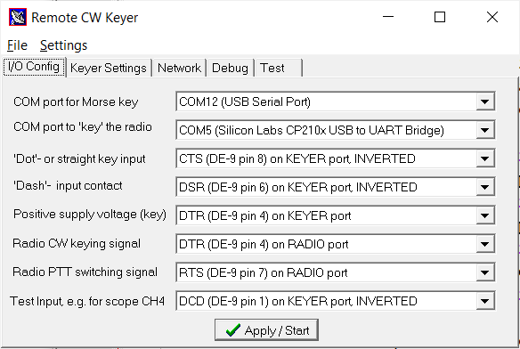
Screenshot of the I/O Config tab with settings for the 'Simple Paddle Adapter'
(in an old version without sub-tabs "I/O", "Rig Control", and "Additional COM Ports")
Notes:
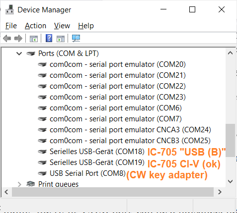
- Finding the right 'COM port' can be a nuisance, because Windows
may assign a new 'COM port number' depending on the USB port
the device is connected to. And even a device's 'friendly name'
doesn't always give a clue - see screenshot above.
- Icom radios, like the IC-7300 used here, often present themselves
as 'Silicon Labs CP210x USB to UART Bridge'.
Your mileage may vary - not only for the 'COM port numbers' !
- An IC-705, connected via USB, was enumerated by Windows
with two COM ports (unfortunately both labelled 'IC-705').
But only one of those to "IC-705" ports can be used for CI-V control !
The other port (called "USB (B)" by Icom) can be configured in
the "Connectors" menu as "Off" / "RTTY Decode" / "DV Data" /
"Weather" (what the heck..) - oh well. So it is your sad duty
to find out which of the two IC-705 COM ports is the right one
for remote control via USB. Don't assume the first port in the list
(with the lower COM port number) is the right one - in the author's
case, "COM19 (IC-705)" was ok, "COM 18 (IC-705)" was not.
At the time of this writing, supporting the IC-705's WLAN
interface by RCW Keyer was out of question, last not least because
the UDP-based protocol is terribly complex, poorly documented,
and on first glance it cannot be used for CW keying with a real
CW key (on/off keying in real time).
- The keying via serial port / Modem control output like DTR or RTS
is not Icom-specific. With a ridiculously simple
radio-keying adapter
(not a microcontroller-based XYZ-Keyer), any radio
with a straight key input can be operated this way.
- If nothing else helps to find the right 'COM port', open the
windows control panel / "Device Manager", expand "Ports (COM & LPT)"
in the tree view, and disconnect / reconnect the USB device
while watching what happens. For example, if the
"Silicon Labs CP210x USB to UART Bridge" disappears and
reappears when unplugging the cable to your IC-7300,
you've discovered the radio's "friendly" but misleading
COM port name.
- Unfortunately, radios with remote control via USB often
only emulate one serial port !
Thus, in many cases, if another application (like wfview)
already uses the radio's USB 'virtual COM port' for remote control
via Ci-V, the port is occupied, and even if the Remote CW Keyer
only needs to drive the modem control lines shown below, it cannot,
because unlike Linux, Windows only allows a single application
to use a particular COM port. A workaround is a serial port tunnel
or a virtual rig port,
to let a third party application control the radio via COM port 'through RCW keyer'.
But keep these advanced topics for later (it involves installing a
Virtual Null-Modem between the third-party
application and Remote CW keyer).
- Certain COM ports (e.g. the ones provided by "VSPE" = 'Virtual Serial Port Emulator')
are not enumerated by Windows. Thus they don't show up
in the combo boxes drop-down list. But you can type their name
(e.g. "COM123") into the combo box directly to use them.
Such an entry may show up later as e.g.
"COM123 (NOT ENUMERATED)" in the list.
- Planned, not implemented yet:
If the program acts as a client, and the radio is controlled remotely
via LAN / WLAN / Internet, the field titled
COM port to 'key' the radio can be set to NONE.
Network-related settings will are to be filled out on the
Network tab, but let's keep that for later.
In the lower part of the I/O tab, inputs and outputs of the serial ports
are assigned to the Morse key and the radio. A lot of different combinations are
possible; for example the radio keying output and / or the PTT output
don't necessarily don't need to be on the port that also controls the radio via CAT/CI-V.
It is even possible to duplicate most of these signals on the 'additional COM ports' as explained
in a later chapter.
At the time of this writing (June 2025), signals available on the two 'primary' COM ports were:
- 'Dot'- or straight key input: For the Simple Paddle Adapter,
where a closed 'dot'-contact pulls CTS to ground, set this to
CTS (DE-9 pin 8) on KEYER port, INVERTED.
- 'Dash' input: For the Simple Paddle Adapter,
where a closed 'dash'-contact pulls DSR to ground, set this to
DSR (DE-9 pin 6) on KEYER port, INVERTED.
- Manual PTT switching input: Rarely used, because when set to 'Semi-BK' or
'Full-BK', the rig itself will start transmitting, or the Remote CW Keyer
will emulate 'Semi-BK' and drive the radio's PTT switching signal.
Details about how to connect a manual PTT switch
(e.g. footswitch, microphone with PTT, etc) are in chapter 3, Circuit diagrams.
When set to 'NONE' (which is the default for this parameter),
the PTT is automatically controlled by the software (emulating 'Semi-Break-In'
with the Tx delay time
and Tx hang time, both configurable
on the Keyer Settings tab).
- Positive supply voltage (key):
One of outputs on the DE-9 connector
for the Simple Paddle Adapter can be configured
to provide a 'supply voltage' for the Morse key adapter (e.g. 'DTR' permanently high,
providing a few milliamperes and about 8 to 12 Volts from a serial port's output signal
- Radio CW keying output: This is typically on a
different COM port than the Morse key. When using a modern Icom radio (IC-7300, etc),
the RADIO port (not only for CW keying) will be the built-in 'Silicon Labs CP210x USB to UART Bridge',
unless a firmware update gives it a more intuitive name.
In Icom's setup menu (e.g. IC-7300: Wrench-and-screwdriver icon, "Connectors", "USB SEND / Keying"),
there is an item labelled 'USB Keying (CW)'. This is typically set to "DTR". To be compatible
with that setting, in the Remote CW Keyer, set Radio CW keying output to
DTR (DE-9 pin 4) on RADIO port.
- Note:
- The Radio CW keying output can be temporarily disabled
on the Keyer Settings tab.
Extra 'CW' outputs (using the 'CW' function on additional COM ports)
are not affected by 'Disable Transmission', and are thus better suited
for a very-low-latency sidetone output with an external tone generator
controlled by an on/off keyed signal.
- Radio PTT switching output: Like the configurable
PTT input, rarely used, because modern rigs automatically switch
between transmit and receive, if either "Vox" (for voice)
or "Break-In" (for CW) is enabled.
In Icom's setup menu (e.g. IC-7300: Wrench-and-screwdriver icon, "Connectors", "USB SEND / Keying"),
there is an item labelled 'USB Send'. This is typically set to "RTS". To be compatible
with that setting, in the Remote CW Keyer, set Radio PTT switching output to
RTS (DE-9 pin 7) on RADIO port.
- Test Input: The state of this multi-purpose digital input can be plotted on the timing scope.
The "pin-to-function" assignment for these is flexible; signals can even be inverted via software
to eliminate the need for e.g. a transistor to invert the 'Dot'- or 'Dash' signal.
Available selections for input signals (from the computer's point of view):
- "NONE" : This signal is not assigned to any pin on any port
- "DCD (DE-9 pin 1)" : The serial port's "Data Carrier Detect" input
- "DCD (DE-9 pin 1), INVERTED" : Same signal, with the polarity inverted via software
- "DSR (DE-9 pin 6)" : The serial port's "Data Set Ready" input
- "DSR (DE-9 pin 6), INVERTED" : Same signal, polarity inverted via software
- "CTS (DE-9 pin 8)" : The serial port's "Clear To Send" input
- "CTS (DE-9 pin 8), INVERTED" : Same signal, polarity inverted via software
- "RI (DE-9 pin 9)" : The serial port's "Ring Indicator" input
- "RI (DE-9 pin 9), INVERTED" : Same signal, polarity inverted via software
Hints in parentheses refer to the pin number of the "DE-9" connector commonly used
on serial ports (aka "D-sub 9-pin connector"). Btw, GROUND is on pin 5 of that connector.
Pins 2 (RXD) and 3 (TXD) can only be used for serial communication (with the exception of
a sidetone output on TXD).
Available selections for output signals (from the computer's point of view):
- "NONE" : This signal is not assigned to any pin on any of the two ports
- "DTR (DE-9 pin 4)" : The serial port's "Data Carrier Detect" output
- "DTR (DE-9 pin 4), INVERTED" : Same signal and pin, but polarity inverted via software
- "RTS (DE-9 pin 7)" : The serial port's "Request To Send" output
- "RTS (DE-9 pin 7), INVERTED" : Same signal and pin, but polarity inverted via software
For a few common adapters for a CW key (paddle or straight), and typical adapters to
actually key the radio, a few 'Predefined I/O Configurations' can be recalled
from the 'I/O Config' tab as follows:
click on 'More' (near the 'Apply'-button) ..
Predefined I/O Configurations   ▶
  Simple Paddle Adapter, CW Keying on separate 'Radio' Port
  Simple Paddle Adapter with CW keying output on the same port (RTS)
  DL4YHF CW Keying Adapter with USB, keying output on separate 'Radio' Port
  DL4YHF CW Keying Adapter with USB, no separate 'Radio' Port
  N1MM footswitch compatible adapter (client side)
  Neither a Paddle Adapter nor a Radio Keying/Control port
If there is no hardware available (to connect a 'real' Morse key to the PC),
the SHIFT- and CONTROL keys on the PC's keyboard can optionally
be used as a poor paddle replacement at very low speeds.
For German users: Die 'Umschalt'- und 'Strg'-Tasten können notfalls
als Ersatz für eine 'echte' Morsetaste verwendet werden.
- Spoiler alert:
- Windows ("GetAsyncKeyState") only seems to poll the PC's keyboard
every 64 milliseconds or so.
Thus you won't have much fun sending CW this way, even at moderate speeds.
But for a quick demonstration of 'squeezing', below say 20 WPM, it's ok.
In the current implementation, when enabled, SHIFT and CONTROL
can be used 'in parallel' to a real Morse key / paddle connected
via serial port as described further above.
2.2.2 Rig Control tab (sub-page on the 'I/O Config' tab)
Under I/O Config / Rig Control, enter additional parameters
for communication with a remotely controlled radio (if the Remote CW
Keyer shall control a radio besides 'keying' it).
- Rig Control Method / Protocol:
- In most cases (e.g. with modern Icom rigs), the CW keyer's remote control uses
the same COM port that is also used to 'key' the radio (shown further above).
At the time of this writing (06/2024), the items in this drop-down menu were:
- No active rig control, only CW keying (or client mode):
In this mode, RCW Keyer does not actively 'control' the local rig (e.g.
change frequency, mode, etc). But is still may 'key' the radio in CW,
or control a remote radio if this instance runs as a network client.
Advanced topic (keep this for later): Even without active rig control,
RCW Keyer may still diplay the current frequency, mode, and spectrum/waterfall
in its own window, when decoding traffic that a third party application exchanges
with a radio through RCW Keyer's Serial Port Tunnel.
- Icom CI-V, using the same 'COM' port (including USB VCP) as for CW keying:
Allows controlling almost everything in a modern ICOM radio, e.g. IC-7300/9700/7610/705.
Compatible with old Icom radios, too (at least for VFO- and Mode control).
- Yaesu FT8x7-CAT, via 'COM port to key the radio':
A half-hearted attempt to control (not just key)
an FT-817ND remotely via Remote CW Keyer. Uses a 'five-byte-command'
protocol that has been phased out long ago. May also work with
FT-857 and FT-897, but not with any other Yaesu radio because
their 'CAT' protocols are too incompatible.
See notes on the KA7OEI FT-817 pages.
- Hamlib NET rigtl via remote TCP/IP server:
Future plan to support non-Icom radios via applications like wfview, flrig, etc.
Not to be confused with the keyer's own Hamlib server
explained further below.
To control other radios (or other station equipment) remotely, use third-party control software
connected to the radio via RCW Keyer's Serial Port Tunnnel.
- Rig Control / CI-V Address:
- Can be used to control certain Icom radios directly (via CI-V protocol),
last not least for a live display on the 'TRX' tab (transceiver control and spectrum/spectrogram).
The (Icom-) radio's CI-V Address can be modified in the radio itself, but this is rarely
necessary. Just keep the radio's default CI-V address, which are listed in the
drop-down selection list, along with the radio model, e.g.:
0x94 (IC-7300)
0xA2 (IC-9700)
0xA4 (IC-705), etc (there will be far more entries than listed here).
Setting this field to "None ('passive' control)" means the program will not actively "talk to"
the radio, but if an unsolicited report (e.g. with the radio's new VFO frequency) arrives,
the program will still decode it, and update the display on the
'TRX' tab.
See also (related subject): Finding the right COM port
(a nuisance with Windows).
- Baudrate (in the 'Rig Control' line):
- For radios controlled via USB (Virtual Serial Port),
set this parameter to 115200 (fast enough for the live spectrum/spectrogram display).
In radios like IC-7300 and IC-9700, the value must match the setting
in the SET menu ("wrench and screwdriver" icon),
Connectors .. CI-V .. CI-V USB Baud Rate.
- Remote Hamlib Net Server URL (for the optional Hamlib client) :
- If the Rig Control Method is set to Hamlib Net rigtl via remote TCP/IP server,
enter the remote server's full URL here. If the server runs on the local machine,
enter something like 127.0.0.1:4532 (4532 is the default port suggested by Hamlib).
Note: The Hamlib 'NET rigctl client' that was integrated in the Remote CW Keyer
has been removed, after experiments with flrig (as a Hamlib-compatible TCP server)
failed. In fact, "flrig" immediately reconfigured a lot of parameters in the author's
IC-9700 - quite annoying if you haven't stored the radio's last 'working configuration'
as a file on the memory card .. another lesson learned.
Thus new experiments will only happen if there is demand from other users
for such a feature.
- Built-in Hamlib Server Port / ☑ enable Hamlib Net Server:
- Enable/disable the built-in 'Hamlib NET rigctld'-compatible server,
and define the TCP port number here. The Remote CW Keyer's
simplified Hamlib compatible server may deliver at least
frequency- and mode information for logbook programs,
'contest loggers', or other software that needs to control
the radio remotely. So far (July 2024), the built-in Hamlib compatible
TCP server has only been tested with WSJT-X / "rig" set to "Hamlib NET rigctl"
(of course, that's a sacrilege for a CW Keyer).
        ,--------------,                ,-------------------,                ,-------,
        | Client, e.g. |                | Remote CW Keyer   |                |       |
        |    WSJT-X,   | <-- TCP/IP --> |    acting as      | <-- USB(?) --> | Radio |
        |    etc ..    |      port 4532 | Hamlib Net server |                |       |
        '--------------'                '-------------------'                '-------'
The default TCP/IP port for Hamlib's "NET rigctrld" server is 4532.
Note: The integrated Hamlib server hasn't got anything to do with the Remote CW Keyer's
own network functionality (which doesn't use ASCII strings
for the communication between client and server, but a bandwidth-saving
binary protocol, which not only carries 'rig control' commands and responses,
but also audio signals and the CW keying bytestream, all multiplexed
into a single TCP/IP socket connection).
If no other applications besides the Remote CW Keyer need to control the rig,
or query the current frequency/mode/etc, then leave the checkbox
☐ enable Hamlib Net Server
unchecked because that's the safer setting ! Also,
due to the lack of user access control, log-in with a password, etc,
don't run the Hamlib Net Server on a port that can be accessed through the internet.
The Hamlib (-'Net'-) server is only intended for use in the local network,
or maybe via VPN tunnel when accessed truly remote.
2.2.3 Additional COM Ports (another sub-page on the 'I/O Config' tab)
Up to three(?) extra COM ports (besides the 'COM port for the Morse key'
and 'COM port to key/control the radio') can be selected under I/O Config,
sub-tab Additional COM Ports.
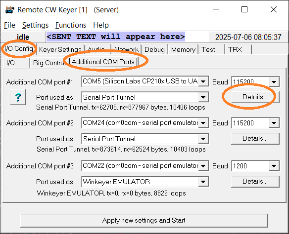
Screenshot of the Additional COM Ports tab
At the time of this writing (2025-07), the following functions could be selected
for each of the Additional COM Ports:
- Winkeyer EMULATOR:
- In this mode, the Remote CW Keyer application shall behave
"like a K1EL Winkeyer itself". This allows e.g. N1MM Logger+
to control the Remote CW Keyer without having a real hardware
interface (Winkeyer 1 or Winkeyer 2).
- Winkeyer HOST ("under development"):
- The Remote CW Keyer application shall act as a host
for a K1EL Winkeyer compatible chip connected to this port,
which may be RS-232, USB, or even a Null-modem emulator like 'com0com'
(COM-zero-COM).
- Serial Text Terminal:
- Mainly used for software testing. Characters received on this port
will be dumped into the text editor on the Debug tab,
and (when in 'terminal mode') characters typed into that editor
will be sent to this port.
- Serial Port Tunnel (e.g. between client and server):
- If additional COM ports are set to this mode on both the
RCW Keyer's CLIENT- and SERVER side, characters sent into a 'tunnel'
(port) on one side will pour out on the other side of the TCP/IP
connection, and vice versa.
This allows e.g. remote rotor control, without the Remote CW Keyer knowing anything
about the rotor control protocol itself, or whatever shall be 'tunneled'
across the single TCP/IP connection between your shack and the remote site.
Serial Port Tunnels also work locally (i.e. between COM ports on the same machine).
- Virtual Rig Port:
- Successor to Serial Port Tunnels, but needs to 'understand' the
protocol used by the real radio, and on the Virtual Rig Port(s).
Allows both (RCW Keyer and 3rd party apps like WFView, WSJT-X,
logging software) to control the radio simultaneously.
The following sections explain these 'Serial Port' functions,
and a setup dialog for the details.
2.2.3.1 Winkeyer HOST and EMULATOR
As already mentioned in the introduction, in Winkeyer EMULATOR mode,
the Remote CW Keyer application shall behave "like a K1EL Winkeyer itself".
This allows e.g. N1MM Logger+ to control the Remote CW Keyer without having a real hardware
interface.
Only the basic features of a 'real' Winkeyer chip were implemented
at the time of this writing (2025-06-15):
- Parse 'immediate' and 'buffered' commands of the Winkeyer protocol,
and send appropriate responses (usually single bytes only)
- Accept commands to change the keying speed. The 'immediate' command,
which N1MM Logger+ sends during the initialisation phase will also
modify the speed indicated in the RCW Keyer's own GUI
(on the Keyer Settings tab).
- Translate characters(!) to be sent in Morse code into such,
using the same generator that sends CW from the RCW Keyer's
own transmit memories and macros,
without affecting those memories of course.
Since RCW Keyer's CW generator produces a sidetone,
Morse code sent from e.g. N1MM Logger+ through the Winkeyer port
will also generate a local sidetone, albeit with a latency
caused by the serial port buffering (remember, those characters
travel as ASCII text with 1200 bits per second, and the entire
character must have arrived before RCW Keyer can start sending it).
- Switch between normal CW speed and "fast speed" on-the-fly and back.
In the Winkeyer2 IC Interface & Operation Manual, this is the
"Change Speed Buffered" command (code 0x1C followed by a value in WPM)
and the "Cancel Buffered Speed Change" command (code 0x1E without parameters).
- 'Merge Two Letters into a Prosign' (code 0x1B followed by two ASCII characters):
Not seen in real life yet, but RCW Keyer internally converts this command
sequence used for Prosigns by Icom, and by RCW keyer itself
(see chapter Morse Decoder Output (-format)).
- Troubleshooting hint:
- Because the implementation of the Winkeyer protocol was
more complex than anticipated, the 'Winkeyer traffic' can be dumped to
the Debug tab (check 'Show Winkeyer traffic
on the Debug tab' in the context menu).
2.2.3.2 Serial Text Terminal
The serial text terminal was mainly used for software testing. Originally,
it was just a 'dumb' terminal emulator where characters received on the
associated port were dumped into the text editor on the RCW Keyer's
Debug tab.
When in terminal mode, characters typed into that editor
are immediately sent to the associated port (they are not buffered
until a line is complete).
Pressing the ENTER key sends "\r\n" (carriage return plus new line).
All 'printing' ASCII characters are sent as such.
'Terminal mode' can be activated through the 'Debug' tab editor's
context menu (right-click).
To some degree, the behaviour of the Text Terminal can be controlled
via the Params field (parameters) in the
Detailed Settings dialog.
2.2.3.2 'Serial Port Tunnels' between client and server
Any of the 'additional COM ports' can be configured for this mode, on both the
RCW Keyer's CLIENT- and SERVER side. Bytes or characters sent into a 'tunnel'
with a certain numeric ID ("tunnel number") on one side will pour out
on the other side, and vice versa.
This allows e.g. remote rotor control using one tunnel, and remote rig control
for third party applications through another tunnel. This works even with
protocols that the Remote CW Keyer itself does not 'understand', e.g. a
custom rotor control protocol, using a dedicated appliction (that otherwise
would only talk directly to the rotor control unit, via local COM port).
All tunnels use the same TCP/IP connection, established by the
Remote CW Keyer between your shack and the remote site - see
serial port tunnel example
sketched in the next chapter. But one TCP/IP connection can 'transport'
multiple Serial Port Tunnels - that's why the tunnel number is configurable.
- Note:
- Serial Port Tunnels in Remote CW Keyer also work 'purely local'.
For example, an old FT-817 could be controlled by Simon Brown's
"FT-817 Commander" through a serial tunnel, while Remote CW Keyer
added the 'CW keying signal' on the COM port connected to the radio:
                          ____"Local" Serial Port Tunnel____
   __________________    /   _________        ________      \       ________
  | FT-817 Commander |      |         |      | Remote |        TXD | Radio  |
  | (using Yaesu CAT)|------| com0com |------|CW Keyer|------*-----|(FT-817)|
  |__________________| COM6 |_________| COM7 |________| COM8 | RXD |________|
                                                 |COM9       |       /|\ CW keying
          ___________                            |           | DTR    |  jack
         |           |       ,-----------------------,  ,-----------------------,
         | Morse Key |-------| Simple Paddle Adapter |  | Simple Keying Adapter |
         |___________|       '-----------------------'  '-----------------------'
In this simple example (without a TCP/IP connection), the rig-controlling
application "thinks" it talks directly to a radio (using only RXD and TXD
on COM6 from its point of view), but in fact it communicates via
(virtual) Null-Modem provided by 'com0com' with RCW Keyer.
In this case, RCW Keyer's serial port tunnel (between COM7 and COM8) passes 'CAT Commands'
(Yaesu slang) from COM7 to COM8, and sends 'CAT Responses' from the radio back from COM8 to COM7.
In addition, it drives DTR (or RTS) on COM8 with the CW Keying signal. Note that
the FT-817, and similar radios of its era, require a simple two-transistor
interface between the COM port's RXD/TXD and the equivalent pins on the
radio's "ACC" connector. Modern radios (e.g. IC-7300) don't need this; they don't even
need the Simple Keying Adapter
because they emulate DTR (or RTS) for CW keying over their internal USB to UART Bridge.
By letting RCW Keyer know the protocol
used over a serial port tunnel, it may eavesdrop on the data exchanged between
the third-party 'controlling application' (e.g. FT-817 Commander, HRD, WFView, N1MM Logger+)
and the radio. That way, RCW Keyer can exctract and show at least the VFO frequency and mode
(for Yaesu radios) or almost everything (for modern Icom radios, including the
live spectrum/spectrogram) in its own window.
2.2.3.3 Virtual Rig Ports (emulate 'their own radio' for 3rd party applications)
Virtual Rig Ports are a successor to RCW Keyer's Serial Port Tunnels.
A Virtual Rig Port doesn't simply pass on commands and responses to / from the radio. Instead,
it mimicks (emulate) a radio for third party applications like logging software or anything that
wants to control the radio. A virtual rig port can even emulate a different radio
than the one actually connected.
For example, WSJT-X, when connected to an IC-7300 through RCW Keyer's serial port tunnel
was running mad, and often ended up with the infamous message box showing
"Rig Control Error", because the IC-7300 was still sending dozens of unsolicited messages per second
- which the old radio control library in WSJT-X didn't expect.
Using one of RCW Keyer's Additional COM Ports
in Virtual Rig Port mode (instead of letting it directly access the radio
via Serial Port Tunnel) fixed this: As long as the third party application
doesn't ask for e.g. 'Scope data' (spectra) or unsolicited VFO reports, it won't receive them,
and won't bail out after receiving anything but the expected response. Phew !
-
                 _Virtual Rig Port_   CLIENT        SERVER
   _________    /   _________      \ ________      ________              ________
  | WSJT-X  |      |         |      | Remote |    | Remote |        TXD |        |
  |  (etc)  |------| com0com |------|CW Keyer|----|CW Keyer|------*-----| Radio  |
  |_________| COM6 |_________| COM7 |________|TCP/|________| COMx | RXD |________|
                                      |COM9    IP                 |       /|\ CW
          ___________                 |                           | DTR    | keying
         |           |   ,-----------------------,       ,-----------------------,
         | Morse Key |---| Simple Paddle Adapter |       | Simple Keying Adapter |
         |___________|   '-----------------------'       '-----------------------'
Example for a Virtual Rig Port: A rig-controlling application on the CLIENT side
'thinks' it's talking directly to an Icom radio, but in fact RCW Keyer controls it remotely.
2.2.3.4 Detailed Settings (dialog for additional COM ports)
Clicking on the 'Details'-button next to the 'Additional COM Port' mode
opens an extra dialog window, where the following parameters can be modified:
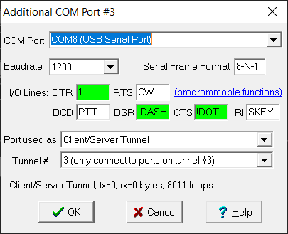
Screenshot of the 'Additional COM Port' dialog,
opened by clicking 'Details' on the 'Additional COM Ports' tab.
- COM Port, Baudrate, Port used as :
- Same basic parameters as shown on the Additional COM Ports tab,
repeated here for completeness.
As in other combo boxes for the serial port selection, if a certain
COM port isn't enumerated by Windows (and thus doesn't appear
with a 'friendly name' in the drop-down list), you can still type it
into the input field manually. Details are here.
- I/O Lines :
- Show the current states of modem control outputs 'DTR' and 'RTS'
(as currently driven if the port is open), and digital inputs
'DCD', 'DSR', 'CTS' and 'RI'. Details about the normal functions
of these signals (from the days of RS-232 and 'terminal equipment')
are here.
For Remote CW Keying, but also as a simple means of remote station control,
"burglar alarm", or whatever, these I/O lines can be abused
for 'general purpose I/O'.
When not used for a special purpose, leave the
input fields next to "DTR", "RTS" (outputs from the PC to RS-232),
and "DCD", "DSR", "CTS", "RI" (inputs from RS-232 to the PC) empty.
The program will then set outputs to defaults, depending on
the COM port usage.
Tokens to assign a special function to these I/O pins are listed
in chapter I/O Control Tokens,
e.g. "CW" and "PTT" for output pins, and "DOT", "DASH", "SKEY" for input pins.
If the selected port is already opened, the Additional COM Port dialog
indicates the current state of the I/O lines by the input field's
background colour:
white : OFF or "logic low"
green : ON or "logic high"
The screenshot shown further above (with DTR=1, RTS=CW, DCD=PTT,
DSR=!DASH, CTS=!DOT, and RI=SKEY)
allows connecting a second Simple Paddle Adapter
to the Remote CW Keyer, with additional gadgets like an on/off keying output
(e.g. to drive an LED or sinewave audio generator) and a manual PTT switching input.
- Params :
- This string input field allows specifying additional parameters. For most 'port uses',
leave this field empty. If something doesn't seem to work, clear it.
The string parser for this field is case-insensitive, so you may type
e.g. Protocol=Icom as well as protocol=icom .
To specify multiple parameters, separate them by commas, e.g
protocol=icom, debug .
- protocol= ... (followed by one of the protocols listed below):
Hint for a 'bytestream decoder' about the protocol travelling over the port.
For example, this allows Remote CW Keyer to eavesdrop on a
serial port tunnel, and extract
e.g. the radio's current VFO frequency, operating mode, receive/transmit status,
and other parameters displayed on its own GUI.
For a virtual rig ports,
at least the protocol must be specified in the 'Params' field.
At the time of this writing (2026), tokens for the protocol were:
- icom : Icom's CI-V protocol, used by almost any Icom radio for decades.
Supports almost everything, including reading spectrum/waterfall data,
thus fully supported in RCW Keyer.
- kenwood (future plan) : Kenwood's text-based 'PC Control Commands', beginning with a
two-character 'Alphabetical command', and ending with a semicolon as the
'Terminator'. Used at least in the TS-480, TS-2000, and possibly many more.
- yaesu_5byte : Yaesu's old, ugly, binary "CAT" protocol, with 5 bytes per command,
and an unpredictable(!) number of bytes in the response from the radio.
Used in old radios like FT-817[ND], FT-897[D], etc, until Yaesu invented
something completely different - see below.
- yaesu_ascii : Also a Yaesu "CAT" protocol,
but now ASII based, with ';' to mark the end of a command or response.
Used in newer radios like the FT-891, FT-991[A], FT-710(?), etc.
Possibly inspired by the 'Kenwood' protocol. Lacks support for
a remote spectrum/waterfall display (at least according to
the official manuals available for the FT-710 in 2025).
Thus not supported by RCW Keyer, except for 'tunneling'.
- debug
Option to show packets or 'blocks of data' in the history on the
Debug tab. One line is shown per packet or block
(e.g. 'Command' or 'Response'). If the protocol is specified (e.g. protocol=icom),
the message data may be converted into a human-readable format, instead of the
default format (=hexadecimal dump for obviously 'binary' data, or ASCII for 'text-
based' protocols).
- terminal
Option to pass anything travelling over this port to the
built-in Text Terminal,
even if Port used as.. is set to e.g. Serial Port Tunnel.
Similar as for option debug, the output format
may be improved by specifying the protocol.
- Tunnel # :
- Controls how data bytes are routed from one port (configured as 'Client/Server Tunnel')
to the other(s). The "ends of a tunnel" (on the server- and any client side)
are connected only when set to the same 'Tunnel Number'.
For example, if the server (e.g. "remote radio site") has an antenna
rotor controlled via a (real) serial port on "Tunnel #2",
then configure the client side's serial port (e.g. on a
virtual null-modem) also for "Tunnel #2" - again, regardless of
the 'COM port number', and regardless of the Additional COM Port index
that you assigned for the rotor control. It's a good idea to write down
all those numbers, or make a sketch as in this example:
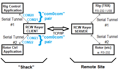
'Serial Port Tunnel' example, using the RCW Keyer's TCP/IP connection between
client and server, two serial tunnels, and two "virtual Null-Modems" (blue).
On either side (client or server), the same tunnel number
can be assigned to multiple COM ports. That's fine as long as
only one of the devices or applications connected to that
tunnel transmit at a time, while the others receive. Since the RCW Keyer is
(usually) not aware of the protocol used over the tunnel, it cannot resolve
conflicts (collisions) when multiple devices transmit at the same time.
Individual bytes will get through, but the receiver(s) will not
be able to identify who sent what.
The configuration dialog shown further above allows setting
the tunnel number to 'ANY'. This was intended for special applications
and software testing. A COM port configured as Client/Server Tunnel
with the 'Tunnel #' set to 'ANY' will receive data from ANY Tunnel,
e.g. from COM ports currently used as Serial Port Tunnels,
on both client- and server side.
- Status (without a label; shown on the bottom of the dialog window) :
- This is a 'life' display of the selected port's current status,
including counters for transmitted and received bytes
("tx" and "rx" from the local serial port's point of view).
When connecting e.g. a terminal program like 'Tera Term' via
com0com to the RCW keyer's additonal COM port for testing,
and typing a character in the terminal, the "rx" counter should
increment.
If a RCW client/server connection is established, and a character
arrives from 'the other end of the tunnel', the serial port's "tx"
counter should increment, and the character appear in the terminal screen.
2.2.3.5 Configuring com0com (Virtual Null-Modem) as bridge to other applications
The free, open-source Null-modem emulator 'com0com' (com-zero-com) can provide
any number of virtual COM port pairs. Their COM port numbers are freely adjustable
(as long as they don't collide with 'physically existing' COM ports, including
USB-to-RS-232 adapters). It's important to modify the default names like "CNCA0" and "CNCB0"
into names that can be enumerated by applications that expect 'normal' COM ports
- see screenshot further below.
After dowloading and installing com0com (used to be at https://sourceforge.net/projects/com0com/ at the
time of this writing), open its setup screen to check the virtual COM port pairs.
Here the author's settings used for various purposes (including
experiments with 'FT-817 Commander', N1MM Logger+, Winkeyer 'Demo',
Rotor control via serial port tunnel, etc):
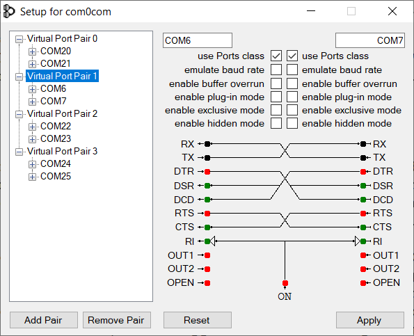
com0com Setup example with a lot of virtual COM port pairs, and their COM port names.
Note the pair with 'low COM port numbers' (COM6+COM7), required for an old application.
To use com0com as bridge between other applications and RCW Keyer,
leave emulate baudrate, enable buffer overrun, etc unchecked on both sides.
Checking use Ports class was sometimes necessary to let the COM ports
provided by com0com appear in the 'COM port' selection boxes of some windows applications,
including Remote CW Keyer itself.
2.3 Keyer Settings tab
2.3.1 'Basic' keyer settings (always available / usable)
At the time of this writing, control elements for the 'Basic Keyer Settings' tab were:
- Key Type: At the moment, only ..
'None' (no key connected, intended for operation as the 'remote server'),
'Straight' (straight key connected to the 'dot' input),
'Paddle, IAMBIC MODE B' (the only mode supported by many modern transceivers)
'Paddle, IAMBIC MODE A' (used by operators who learned CW with an old 'ETM' key)
'Basic iambic keying without dash- and dot memory'
- Speed (WPM): The speed in 'Words per Minute per PARIS test'
can either be entered numerically (edit field),
or by moving the horizontal slider via mouse or cursor keys.
The slider's upper endstop is around 48 WPM, similar as Icom's built-in keyer.
The numeric input field accepts higher speeds for HSCW-enthusiasts and testing.
- Sidetone on TXD: A low-latency
sidetone can be tapped from the serial port's
TXD output (serial data), with either 480 or 960 Hz for reasons
explained here.
If that's too unpleasant, add a sinewave oscillator controlled by the
'CW keying' output, or an audio bandpass filter to convert the
rectangular wave into a sinusoidal one. Other alternatives are presented
in the extra chapter CW Sidetone.
- TX delay time: Number of milliseconds between activating
the PTT, and sending out the first dash ot dot, when changing over from
receive to transmit.
- TX hang time: Timeout in milliseconds before the keyer
switches back from transmit to receive (without activity on the PTT-
or Morse key input). When used on the Server side,
when the TX hang time expires (without activity from the client that
currently 'has the key'), other clients with 'TX permission' may take it
and start sending. With a low TX hang time, this is similar to
'semi-BK' operation as supported by most rigs and amplifiers.
'Full-BK' aka 'QSK' doesn't make sense due to network latencies.
- [ More ] : This button opens the same submenu
as in the main menu under 'Settings'..'More Keyer Settings':
  ☑ Watchdog against 'Stuck Paddle Input' (10 seconds)
      Stops transmitting after 10 seconds 'key down' without a transition on an input.
  ☐ Debounce Paddle Inputs
      Prevents erroneous dashes or dots 'in memory' in certain Iambic keyer modes,
      at the expense of a slightly higher latency between paddle input and CW output.
  ☐ Use Keyer Speed from an external speed potentiometer
      Only has an effect when using an 'intelligent' CW keying adapter
      with a potentiometer to adjust the keying speed. See next chapter.
  ☐ Use VFO knob attached on external CW keying adapter
      Only has an effect when using an 'intelligent' CW keying adapter
      with an interface for an external 'VFO knob' (rotary encoder).
  ☐ Use 'shift' and 'control' key as paddle replacement
      Just a gadget. Can be used instead of a real key, at low speeds.
  ☐ Disable Transmission ('SIM TX', only CW sidetone output)
      Useful for code practicing or adjusting the speed without causing QRM.
      The transmitter will not be keyed, but "CW" can still be routed
      as an on/off keyed signal to any Additional COM Port.
In the lower part of the "Keyer Settings" tab, the same Timing Scope
is displayed as on the 'Test' tab.
The speed can be modified on the fly (via slider), while operating the paddle.
Each tick on the scope's timestale represents one 'dot' interval.
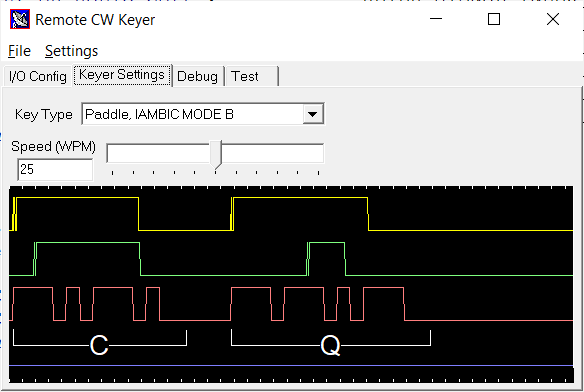
Screenshot from the 'Keyer Settings' tab from an early version of the 'Remote CW Keyer',
with the Timing Scope indicating bouncing contacts from a Kent key.
At 25 WPM, a 'dot' interval (and thus tick on the timescale) is theoretically
1200 Milliseconds / 25 = 48 Milliseconds
long, where 1200 ms is the length of a 'dot' at one "Word" ("PARIS ") per Minute.
2.3.2 'More' keyer settings (for Winkeyer or DL4YHF's USB CW Keying Adapter)
Since adding support for Winkeyer (RCW Keyer acting as a host for a K1EL-Winkeyer-compatible adapter)
and DL4YHF's PIC18F25J50-based 'CW Keying Adapter', the space on the 'Keyer' settings tab
(described in the previous subchapter) was too short for additional settings.
Settings specific to using a Winkeyer (or DL4YHF's CW Keying Adapter with a cheap PIC microcontroller)
have been moved into the 'More Keyer Settings' menu (can be opened via main menu or the already mentioned
'More'-button on the keyer settings tab).
- Use Keyer Speed from an external speed potentiometer
- When available, RCW Keyer tries to retrieve the CW keying speed from a 'speed pot',
for example on a K1EL-Winkeyer-compatible chip (planned) or from
DL4YHF's CW Keying Adapter (with PIC18F25J50 and USB / Virtual COM Port).
- Use VFO knob attached on external CW keying adapter
- So far, this is only possible with DL4YHF's CW Keying Adapter (with PIC18F25J50 and USB / Virtual COM Port).
2.4 Audio Settings
This tab allows selecting audio devices for input and output.
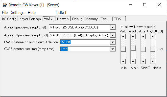
Screenshot from the 'Audio Settings' tab.
- Audio input device (optional)
- The audio input device is mainly used on the Server side
- it is either a modern Icom's built-in audio device for reception,
or a soundcard's "line-input" connected via audio cable to the receiver's headphone output,
or (better, but not always available) the transceiver's "ACC" connector which often
has an audio output with a constant level (e.g. 200 mV RMS regardless of the rig's
"Volume" pot setting). Please consult your radio's manual for details.
Under Windows, an IC-7300's built-in audio device (from where the RX audio signal
could be tapped via a single USB cable), the device name was a misleading and
ambiguous "Mikrofon (2- USB Audio CODEC)".
Note: If Windows really thinks the radio (receiver) is a "Microphone", it may help
to "Disable all sound effects" in the Windows "Sound Settings", You may
find that by right-clicking on the 'Speaker' icon in the task bar,
"Open Sound Settings" .. "Sound" (scroll down to "Input") ..
"Chose your input device" (XYZ-Microphone) ..
"Device Properties" .. scroll down to "Related Settings / Additional device properties",
click there to open yet another window titled "XYZ Microphone Properties",
switch to tabsheet "Enhancements", or whatever they will call it next time,
and CHECK "Disable all sound effects" to stop Windows from messing around
with the audio signal. Phew.
At least, on the author's PC, "Disable all sound effects" turned off the
annoying automatic gain control for what Windows thought was a "Microphone".
Only with the audio input's automatic gain control off, the Remote CW Keyer's built-in
Audio CW Decoder could properly decode Morse Code fed into the PC through
the notebook's built-in microphone.
- Audio output device (optional)
- The audio output device can be used to generate a 'local sidetone'
through e.g. the PC's integrated audio playback device, headphones or speakers.
When operating as a Client, the same decive will also output the remote
receiver's audio signal.
When operating as a Server, the audio output device may be routed to the
transmitter's modulation input (if you really insist on using the Remote CW Keyer
to send voice).
- CW Sidetone on audio output device
- Frequency of the sidetone when emitted through the 'Audio output device'
- Note about sidetone output via 'audio device':
- Compared with the sidetone
on the COM port's TXD output, the latency is a bit higher,
but -last not least due to the carefully shaped rising and falling
edges of the synthesized audio tone- it's more pleasant for listening.
- CW Sidetone rise time (ramp time)
- Rise- and fall time (thus "ramp time") in milliseconds.
The lower, the "harder" the keying (more sidebands, in the extreme case
a horrible "click spectrum" as sometimes heard and seen on shortwave,
when ignorant operators run their Killerwatt-amplifiers in class C,
destroying the carefully shaped RF envelope produced by the rig itself).
The 'Volume adjustment' sliders on the right side of the 'Audio' tab adjust the following:
- A-in : Audio input level
- Additional gain control for the audio input (if you don't want to modify
the gain in the Windows 'volume mixer', or whatever they call it now).
Note: This "gain" (or attenuation) is applied in the internal digital signal
processing chain. It does not adjust the volume in the "soundcard" / microphone gain
or the audio processing in a CI-V controlled Icom radio.
- A-out : Audio output level
- Additional gain control for the audio output. Also applied internally, by multiplying
the digital samples in the internal DSP chain, before sending them to the output.
- SideT : Sidetone level
- Amplitude of the internally generated sinewave that will be added to the Audio output
(digital samples from the program's internal DSP).
- Net-in : Volume of audio signals received from the network, including "signalling tones".
- If the audio signal received from a remote server (web-SDR-like) is too weak or too loud,
this slider provides an amplification or attenuation ranging from 0 to 20 dB.
The center position of these "Volume adjustment" sliders, 0 dB (marked by a horizontal line)
means "neither amplify nor attenuate".
Other controls on the keyer's "Audio" tab:
- ☑ allow 'Network audio'
- Used on the Server side, this option allows sending audio via network (to clients that also use
the Remote CW Keyer application, but also to clients using a web-browser to just
"listen" to the remote radio). So remember to check this option when running the
Remote CW Keyer as a kind of "web sdr" (serving multiple receivers, but all doomed
to listen to the same frequency, because an IC-7300 isn't a Kiwi SDR ..)
- ☑ Decode CW from audio signal
- Activates the experimental 'CW decoder for audio signals',
fed either from the locally connected radio (using the
Audio Input Device selected further above)
or the audio stream received via network from the remote server
(if, on the server side, 'allow Network audio' is checked).
- ☑ Sidetone when keyed ON THE RIG
- Special feature to avoid confusion for remote users when the 'sysop' keys his own radio locally,
i.e. with the Morse key plugged directly into the transceiver (without
RCW Keyer in between). With this option SET, RCW Keyer will notice when
the tranceiver goes 'on air' by itself (without being remotely controlled),
and in that case, quickly turns on what the Icom IC-7300 "Full Manual"
(A7292-4EX-11 page 163) calls
'Beep and speech output setting to ACC/USB'. This actually includes
the rig's locally generated sidetone, which per default is only routed
to the rig's speaker and headphone output, but not to the
'USB audio output' (internal soundcard delivering the received audio signal).
With this flag set, the rig (at least an IC-7300) adds the CW sidetone
to the audio signal from its internal soundcard, so other users will notice
that the radio is currently being used by the sysop.
When transmitting REMOTELY (via RCW Keyer), the rig's sidetone output on
'USB Audio' is turned off again (by RCW Keyer) to avoid bugging remote users
with their own, network-delayed, CW transmit signal.
With this flag unchecked, RCW Keyer will not touch the settings you made
in your Icom rig under 'Connectors' .. 'XYZ AF Beep/Speech Output' at all.
Later versions of the Remote CW Keyer may have more control elements than listed here.
Notes and hints ("audio related"):
- If the Remote CW Keyer controls a modern Icom radio (via CI-V),
the audio volume of the radio's internal speaker
can be modified by editing the parameter listed as
AudioVolume (along with many others) on the RCW keyer's
'Debug' tab.
- You can check the audio input without hearing it (e.g. on the Server side)
by plotting it along with other signals in the timing scope:
Right-click into the scope (curve area), and check 'Show Audio input' in the scope's
context menu. Also check 'Free Run (don't wait for trigger)' to let the scope run
even if there is no trigger event from the Morse key.
2.5 CW Sidetone (overview and methods to generate it)
Remote CW Keyer supports multiple methods to generate an audible CW sidetone.
When operated locally (Morse key connected directly to the rig), you don't need any
of these because the rig itself provides a clear, low-latency sidetone usually adjustable
in volume and frequency. But for reasons explained in the
'Technical Details' section of this document,
this doesn't work for true remote operation (with "the internet" and two
service providers between client ("operator's shack") and server (remotely controlled radio).
Methods to generate the CW sidetone, roughly ordered by increasing latency:
- Use an external key / keyer with integrated sidetone, like
the author's QRP PIC Keyer, ETM-5C, Winkeyer, etc.
- Use RCWKeyer's Simple Paddle Adapter, and tap
the sidetone on the serial port's TXD output (serial data abused to generate e.g. a symmetrical
480 or 960 Hz square wave, selectable on the Keyer Settings(!) tab)
- Use the PC's soundcard, or built-in speakers to emit a locally generated sidetone.
That's configurable on RCW Keyer's Audio(!) tab, including volume, frequency,
and envelope shaping (rise and fall time in milliseconds).
- Accept the network delay, and rely on the sidetone generated by the remotely controlled rig.
Some rigs don't, other do emit their internally generated CW sidetone to their audio output.
In modern Icom rigs (e.g. IC-7300), this is even configurable for the built-in USB audio output.
Not a real solution, but possibly ok with a straight key at low speeds.
Looking at the above, there is another catch (actually the reason to write this summary):
Users of the remotely controlled radio may be irritated by the 'long delayed' echo from the sidetone generated
by the rig itself, when keying the radio during their own 'TX'-overs. But for others (listeners simultaneously
logged into the remote server), it helps to hear what is actually been sent (transmitted "on air")
at the moment - so they will actually hear both sides in a QSO, instead of only hearing the radio's
received signals when e.g. the sysop uses his radio locally for transmission, with the
Morse key connected locally (not via Remote CW Keyer). For that purpose,
RCW Keyer can remotely turn the sidetone generated by the rig itself on and off, as explained
here (under 'Audio Settings': Sidetone when keyed ON THE RIG).
2.5 Network Settings and Client/Server operation
Two instances of the Remote CW Keyer can 'communicate' with
each other via local network (Ethernet- or Writeless LAN).
A remote connection 'via Internet' may be possible, but more
difficult to set up, because the remote server
needs to have a fixed IP address to be easily connectable
by the client.
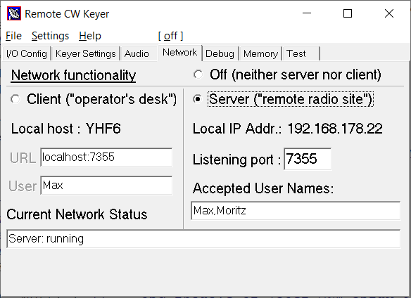
Screenshot of the Network tab
At the time of this writing, the 'Network' tab was only
used to configure the network access (IP addresses, ports,
and access control). Various kinds of data (like the
CW keying signal,
rig control, audio,
spectrum data, serial port tunnels,
etc) can be enabled/disabled on other tabsheets of the program.
Blue-coloured labels on this (and other) tabs can be clicked.
Clicking those 'link-like' labels opens the manual, and
(if the web browser permits) scrolls to the relevant position.
- Note:
- Besides the network functionality described in this chapter,
the Remote CW Keyer may emulate
a 'Hamlib NET rigctld'-compatible server.
2.5.1 Network Functionality
The 'network functionality' is controlled via the radio buttons
in the upper part of the 'Network' tab:
◉ Off (neither client nor server but local operation)
○ Client ("operator's desk")
○ Server ("remote radio site")
2.5.1.1 'Windows Defender Firewall'
When switching from e.g. "Network functionality : OFF"
to "Server" for the first time, DON'T PANIC - you may see
a 'Windows Security Alert' like this:
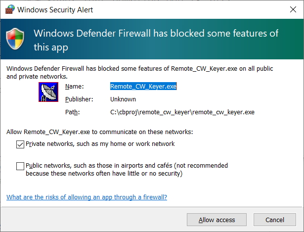
'Windows Defender ' has blocked some features of this app'
- expect to see this, or a similar 'Security Alert' when trying to
start the Remote CW Keyer's 'network' functionality for the first time.
Fortunately, Windows remembers if you 'Allow access' for later settions.
Without 'Allowing access', the program can neither operate as a server
(on the "remote radio" site), nor as a client (on the "operator's desk").
For details about the CW keyer's TCP-based network protocol and troubleshooting,
see chapter 3 in this document.
To establish a connection "over the internet", not just within the local network,
it may be necessary to check both items in 'Windows Defender Firewall':
  Allow Remote_CW_Keyer.exe to communicate on these networks:
   ☑ Private networks, such as my home or work network
   ☑ Public networks, such as those in airports and cafés
To open the 'Windows Defender Firewall' control panel again, to check or modify
the settings later, either press the Windows key + "S" (Search), and enter e.g.
"Windows Defender Firewall". Alternatively, open the windows "Control Panel"
(the one that shows "Adjust your computer's settings"), and navigate through
Control Panel > All Control Panel Items > Windows Defender Firewall .
The panel should now show something like "Help protect your PC with Windows Defender Firewall".
On the left side, there's a link to Allow an app or feature through Windows Defender Firewall.
Click on it.
In the list of known applications, scroll down to "remote_cw_keyer".
If you had installed older versions, or installed the program multiple times
into different folders, there may be a confusing number of entries all with the
same name (unfortunately Windows doesn't show the full path of the executable
in this list, but only the name). If so, to clean up this mess, select
the 'remote_cw_keyer' items one by one, and click 'Remove'
for each entry. Then, start the Remote CW Keyer again, and as soon
as it tries to act as client or server, the 'Windows Defender Firewall'
will pop up with the 'Windows Security Alert' shown above again.
2.5.1.2 Operation as Server
With the radio button
◉ Server ("remote radio site")
checked on the 'Network' tab, the program will act as a simple
TCP (not HTTP) server.
This functionality is intended to be used on the "remote radio site"
(or "side" if you prefer to see it from the network's point of view).
The server can accept a limited number of remote clients over the
internet, or through your local network.
As a minimalistic access control, if you decide to let the program run
as server through 'the internet' (which possibly requires port forwarding
in your DSL router or similar network equipment), enter the name of all
'Accepted User Names' in the right part of the 'Network' tab.
A remote client (CW operator) can only connect successfully if
his user name matches one of the names in the comma-separated
list of the server's "Accepted User Names".
Before diving in deep with a real server accessable "via Internet",
the client/server functionality should be tested in a local network.
For that purpose, the Local IP Address
is displayed on the 'Network' tab. For the server itself, it's not
important to know its own IP address (neither the "local" nor the public
"world-wide" IP address). Only the server's listening port
is user-configurable - the rest (IP address or hostname) is dictated by
the machine's network settings, or (for the public IP address) the
port forwarding settings in your network gear, and the IP address
assigned to your DSL router (or similar) by your internet provider.
More about running a server accessable 'from the internet' will follow
in a future chapter. An example to test client / server communication
in the same local network follows here.
If, on the program instance that runs as a server, an audio input device
is active (selected for input from the radio to the server), the server will
distribute that audio signal to all clients. In other words, all clients
connected to the server will be able to 'hear' the received signal if they wish.
As the sysop of the server, it's your decision to allow streaming audio
directly from RCWK - see Audio Settings tab,
☑ allow 'Network audio'.
- Note for German users (radio amateurs) about Remote Operation:
- Before making your transmitter available for other
"Class A" licensed radio amateurs, please read
§ 13a, "Remote-Betrieb", published in "Bundesgesetzblatt Nr. 160"
in June 23, 2023, and applicable ("Inkrafttreten")
one year after being published - in other words, since June 23, 2024.
Quoted from the above (German Bundesgesetzblatt Nr. 160, § 13a):
- (1) Der Remote-Betrieb einer Amateurfunkstelle ist nur durch Inhaber
einer Zulassung zur Teilnahme am Amateurfunkdienst mit dem
Berechtigungsumfang der Klasse A gestattet.
Im Fall einer Klubstation ist der Zugriff auf Mitglieder
einer Gruppe von zugelassenen Funkamateuren im Sinne von
§ 2 Nummer 3 zu beschränken.
(....)
- (4) Der Inhaber des Rufzeichens nach § 14 Absatz 1 Satz 1
hat auf Verlangen der Bundesnetzagentur Auskunft über den Kreis
der zum Remote-Betrieb berechtigten Funkamateure zu geben.
- (5) Der Inhaber des Rufzeichens hat einen unberechtigten oder
missbräuchlichen Zugriff auf die Amateurfunkstelle durch Maßnahmen
auszuschließen, die dem Stand der Technik entsprechen.
Im Fall einer Störung muss der Inhaber des Rufzeichens
die Amateurfunkstelle jederzeit auf Anforderung der Bundesnetzagentur
abschalten können. Der Inhaber des Rufzeichens muss sicherstellen,
dass er während des Betriebs der Amateurfunkstelle unter den nach
Absatz 3 Satz 2 und 3 angegebenen Kontaktdaten unverzüglich
telefonisch erreichbar ist (...)
Mit anderen Worten: Remote-Betrieb ist zwar in DL seit dem 23. Juni 2024
für Klasse A erlaubt, der Betreiber der fernbedienten Station muss aber
jederzeit in der Lage sein (auch nach Telefonanruf durch die BNetzA),
bei der fernbedienten Station "den Stöpsel" ziehen zu können !
Der hier beschriebene "Remote CW Keyer" ist dazu im Zweifelsfall
(z.B. bei einem Programmabsturz) nicht in der Lage.
Bei 'echtem Remote-Betrieb' ohne Anwesenheit des Betreibers 'im Shack'
empfiehlt sich der Einsatz eines 'GSM-Fernschalters' / 'GSM-Steckdose'
mit eigener SIM-Karte / Mobilfunk-Zugang, um im Fehlerfall der gesamten Station,
inklusive Transceiver, jederzeit 'den Saft abdrehen zu können'.
2.5.1.3 Operation as Client
With the radio button
◉ Client ("operator's desk")
checked on the 'Network' tab, the program will try to connect
a remote (TCP-) client described in the previous subchapter.
To use the program as a client (that connects to a
remote server), you need to have a User name (assigned to you
by the Sysop). The User name will not be visible
by other users. But your Callsign will be visible to others
(at least when you transmit, you are obligated to send it
periodically anyway, so the callsign isn't a secret anyway).
If after the server positively identified the client
(by his User name, which must have been configured by the server's operator),
Morse code sent by the client's operator will be converted into a
low-bandwidth
bytestream, which will be sent via TCP/IP to the server.
Note that in this direction, the signal is not as an audio signal
but as a precisely timestamped
sequence of 'key down / key up' commands. Details and the format of this
bytestream are specified in chapter 3.
The received signal (picked up by the radio at the remote site)
is sent from server to client over the same TCP/IP connection, not as an
'on / off keying' signal, but as a real audio signal at a low sampling rate,
using moderate audio compression to reduce the TCP/IP stream bandwidth
even further. The sysop of the remote server may disable streaming audio
through RCWKeyer's own TCP connection, in favour of other audio streaming
methods (like SonoBus, Mumble, etc). That is configurable on RCWK's
Audio Settings tab,
☑ allow 'Network audio'.
2.5.2 Network Status
The text field 'Current Network Status' shows a summary of ..
- The program currently running as Server, Client, or without any
network functionality ("off")
- When running as server: The number of remote clients currently logged in
- When running as client: The log-in status, remote server address,
and permissions granted by the server's sysop
- Number of bytes transmitted ("tx") and received ("rx") over the network socket
More 'network diagnostics' can be invoked through the application's main menu
("Settings".."Network Diagnostics" and "Report Test Results on the Debug Tab").
If, when configured as CLIENT, RCW Keyer can't connect the remote SERVER,
the network status may toggle between ..
- Client: Trying to connect server ...
- Client: Waiting (5,4,3,2,1 seconds) before trying to re-connect
.. then the remote RCW Keyer Server may be off-line, the server URL (including the port number)
may be wrong, or there is a network problem. In the latter case,
proceed as explained in chapter 3, Network troubleshooting.
2.5.3 Accepted Users and Permissions
As quoted above, for 'real' remote operation, some authorities require
the operator of a remotely controlled transmitter to restrict
the access to authorized users. The text field 'Accepted Users and Permissions'
must be filled out by the 'sysop' of the server. The format is a simple list
of comma-delimited user names. For each user, the sysop may define permissions,
i.e. specify if a certain user is allowed to talk to other users (via internet,
not radio), transmit (via radio, e.g. depending on his license class),
or even 'control the rig' (e.g. change the frequency). These 'permissions'
are encoded as a decimal number (actually a bit combination, listed below),
separated from the user name via colon. A user name may consist
of letters, digits, and the underscore character.
Example:
Accepted Users and Permissions:
Max:0,Moritz:7
Decimal bitmasks for 'permissions' :
- 0 (default when not specified at all) : No extra permissions
This user (like 'Max' shown in the example) may connect the server
and will receive the radio receiver's audio signal, but he can
neither 'talk' to other users, nor transmit, nor control the remote rig.
- 1 : "permission to talk via internet"
If this user has an audio input device
selected in his client software, the audio signal picked up by that
device may be sent to the remote server. The server will distribute
this audio stream to other users currently logged, if they also have
"talk" permission. This feature was intended for CW training, to allow
the teacher / instructor (who usually will run the server) to speak
with the students (clients) if they are still at the begin of their
'CW career'.
- 2 : "permission to transmit on the radio"
If this user currently 'has the key', his Morse code transmission
directed to the server will be passed on to the remotely controlled
radio's CW keying input (as configured on the
I/O Config tab).
If there is no remotely controlled radio connected to the server at all,
the Morse code keying signal will be 'relayed back' (as a byte stream
with an exceptionally low network bandwidth) to all
currently connected clients (users). This "on/off keying" stream
may be converted into an audio tone on the client side.
This way, OMs plagued by QRM or bad propagation can rag-chew
in CW 'via Internet', without the need for a dedicated voice-over-IP
server or whatever.
- Note:
- Even if the server's sysop has granted transmit permission
for a certain user (by user name) this way, the user will only
be able to transmit if the remote client not only sent a correct
user name, but also a callsign. Without a callsign,
no user can transmit. The user may modify the callsign (for example,
use his private call when operating from home, or with a /p or /m
suffix when operating portable or mobile, or with the club station's
callsign when operating, or even with a /r for "remote" appended
if that is required by the local authorities. The 'Remote CW Keyer'
(server side) doesn't care about the callsign ..yet.. as long as
the callsign sent by the client isn't empty.
- 4 : "permission to control the rig" (change frequency, etc)
This option (bitmask) may allow the user to 'control' the remote radio.
In most cases, a sysop will only allow this for himself, because he
is responsible for the output power limits, bandplan-compatible mode, etc.
- Note:
- Even SWL's (Shortwave Listeners without an amateur radio callsign)
may control the rig, if the sysop permits (for their 'secrect user name').
"Controlling the rig" doesn't necessarily mean "permission to transmit".
- 8 : "permission to act as the System Operator"
This option allows the sysop to log into the remote station,
and modify parameters that others (even users with the 'permission to transmit'
or to 'control the radio') cannot.
For example, only the sysop can modify a user's permissions, change the
allowed frequency ranges, power limits, and sent messages via
chatbox that automatically pop up on the
currently connected clients.
The above numbers can be added (or "bitwise combined") to assign more than one
"permission" per user. For example, "Moritz:7" has the three permissions listed
above (thus he may talk (1), transmit (2), and control the rig (4)).
But, as already noticed, if user "Moritz" doesn't fill out the 'Call' field (callsign)
on the 'Network'-tab / Client side (left), he will not be able to transmit.
2.5.4 Built-in HTTP Server and the 'Admin Password'
.. is in a very experimental stage; too early to be completely documented here ..
At the moment, the built-in HTTP server was only used to check the connection
from the office PC to the remotely controlled radio at home,
after experiencing problems to establish a 'raw TCP/IP' connection
to the server's listening port (7355 at that time).
It later turned out that the 'secure' infrastructure blocked any TCP/IP
port except port 80 (the well-known port for HTTP), which by the way
was the reason why none of the nice web SDRs (Kiwis, Twente, ..)
could be listened to during the lunchbreak.
By allowing HTTP besides the 'raw' TCP/IP (used for remote CW keying),
the program's build-in Server for the "remote radio site" can also be
accessed from any web browser (if you remember the IP address, and can
convince your mobile browser to treat the input as an address instead of
'googling' for what you entered). The HTTP server only supports HTTP,
not HTTPS, so to prevent accidental visitors from receiving any info,
the URL (entered in the browser) must have at least a valid user name
in the query string, e.g.:
http://servername.dynv6.net:7355?user=Moritz&pwd=Admin
where servername.dynv6.net was the server's public URL (yours will be different),
7355 was the ham-radio-friendly port number (in the author's case, blocked by paranoid infrastructure at the QRL),
Moritz was one of the 'Accepted User Names' (see Network Settings tab - yours should be different),
and Admin is a really stupid password to log in 'as administrator' (yours must be different).
Being the 'server administrator' hasn't got anything to do with elevated privileges
for a windows application. Only the 'server administrator' can log into
his own server (e.g. using a mobile phone when being on vacation) to read out
e.g. the server log, disable access to the radio, stop it from being 'keyed',
or even shutdown the entire server (not only the HTTP part, but also
the 'remote CW keying' part), etc.
Note: If a visitor tries a wrong password ("pwd=" in the query string),
he will be immediately kicked out of the system without even getting a response,
and his IP address will be automatically blacklisted for some time.
If the visitor tries another user name (or password) before the blacklist-time expired,
the blacklisting timer will restart. Thus, after accidentally entering
a wrong user name or password in the URL (as part of the query string),
don't immediately try again but wait for a minute.
2.5.5 Client/Server test in the local network
Trying to keep this as simple as possible.. but step-by-step:
- Install and start the Remote CW Keyer on machine 'A',
in your local network (Wireless LAN or Ethernet doesn't matter;
what matters is that Windows and its built-in ' allows
machine 'A' and 'B' to communicate with each other over TCP/IP).
- On 'machine A', switch to the application's "Network" tab and check
◉ Server ("remote radio site")
Machine 'A' will be acting as server.
If Windows bugs you with something like "Windows protected your PC",
because from its point-of-view the Remote CW Keyer is an
"unrecognized app", proceed as described here.
- Write down the 'Local IP Address' displayed on the 'Network' tab
(this is the SERVER'S IP address for the test in the local network)
- Write down the 'Listening port' (the default was 7355, this is the port on which the server listens for clients)
- Check the Network Status - it should show something like
Server: running, no client connected, tx=0, rx=0 bytes
- Install and start the Remote CW Keyer also on 'machine B',
connected to the same local network as 'machine A'.
- On machine 'B', switch to the application's "Network" tab, and check
◉ Client ("operator's desk")
- On machine 'B', Under 'Client' (i.e. in the left half of the "Network" tab),
in the 'URL' field,
enter the Server's IP address (you wrote that down from machine 'A', five steps above),
followed by a colon (':' to separate the IP address from the port number),
followed by the server's 'Listening port' (you wrote that down from machine 'A', four steps above).
- Under 'Client' / 'User': Enter one of the user names accepted by the server.
(With the default settings after a fresh installation, try Moritz because
with that configuration, Moritz is the user with the
permission to do everything (7), including transmit.
Later, if you dare to make the server accessable "via Internet", don't forget
to delete "Max" and "Moritz" from the list of users on the server side, because anyone
who read this manual will try to access your server with that name.)
- Under 'Client' / 'Call': Enter a callsign here, because
without a callsign, the server will not allow the user to transmit,
for reasons explained here.
- Still on machine 'B', check the Network Status - here, it should show something like
Client: logged into NNN.NNN.NNN.NNN:PPPP, tx=789, rx=1234567, may talk, transmit, control the rig.
(where NNN.NNN.NNN.NNN is the numeric IP address, just in case you entered the server's hostname instead of a numeric IP address;
PPPP is the port number, followed by the number of bytes transmitted and received,
and finally a summary of the permissions granted to the client by the server,
depending on the user name and callsign that the client has sent to the server).
For the next step (sending Morse code from client to server, and letting the server "key" the radio),
select the COM port where the Morse key is connected (on the client side),
and the COM port that 'keys' or even 'controls' the radio (on the server side),
on the keyer application's I/O Config tab.
To hear the received audio on the client side, check the Audio Settings
in the Remote CW Keyer application, and (for 'modern' Windows versions) in the
Windows audio control panel, "privacy settings", or whatever they call it now.
Don't forget to check
☑ allow 'Network audio'
because otherwise, the instance running as server will not pass the audio signal from the radio to the network.
See also:
Hardcore network troubleshooting / Windows Firewall trouble /
TCP/IP ports hijacked by other applications / Port forwarding, etc
in Chapter 3, Network troubleshooting .
2.6 Debug tab / Error History / Parameter List
The 'Debug' tab is a text edit control, primarily intended to emit
error messages and 'test results' from the program.
If a modern Icom radio is connected via CI-V, a lot of parameters and
settings that this application reads from the radio can be
listed and even edited
on the Remote CW Keyer's Debug tab (including settings
that don't have their own visual control element in the GUI).
The amount of info displayed on the Debug tab is configurable
through the context menu (details in the
next subchapter).
Besides that, if the keyer is in 'Elbug' mode, characters sent in Morse code
are decoded (by the 'Elbug' itself), and may be emitted as text into this window.
Different text colour backgrounds indicate if a line of text is an error (red),
warning (yellow), or just an info (white background). Morse code decoded
while sending via built-in keyer has a light blue background.
- Note:
- The built-in keyer also emits decoded Morse code
into the Timing Scope, where,
for the operator, it's more fun to watch during a QSO,
or for personal CW training.
The display format of a few 'special characters' and
Morse code specific prosigns is similar as
the one used by Icom's built-in "Memory Keyer".
For example, "...-.-" (Silent Key) appears as ^SK .
More on that later.
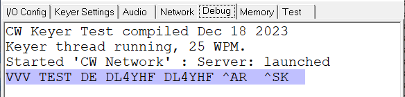
System info and Morse decoder output on the 'Debug' tab
On the 'Debug' tab, you may find error messages
as in the following example (copied from the 'Rich Text' editor):
CW Keyer Test compiled Jan  1 2024
Keyer thread running, 25 WPM.
Client: launched
Client: Trying to connect 127.0.0.1:7355 ...
 .. failed: Connection refused
Error messages like the one shown here are often translated from
the network 'Socket service' layer. These messages are sometimes
quite cryptic, or don't really hit the spot. There's a list of network-related
error messages in the appendix,
along with what may have caused them. For example,
the "Connection refused" often doesn't mean that the remote server
'refused to accept a connection from the client', but
the specified port was not opened yet (the remote
IP address was ok, but the server wasn't running on that machine).
Besides network error messages, there may be error messages
and warnings shown on the 'Debug' tab during initialisation and
normal operation. Most of them should speak for themselves,
so here just a few ("those who need some explanation"):
- Configuration not finished yet (and possibly 'switching to Config tab')
- After installation or a RWC Keyer software update,
entries on the I/O Config or Rig Control tab
have been made, but the button labelled
Apply new settings and Start
has not been clicked in a previous session.
When closing the application, the program saves its state
("running" or "waiting to be configured"),
and when starting the next time, it waits until
you (the user) has confirmed the settings are ok
by clicking that button.
- Could not open serial port 'COMxyz'
- This often happens with Windows after plugging a USB/RS-232 adapter
(or similar) from one port on the PC side to another:
When plugged into a different USB receptacle (or USB hub),
Windows often assigns a new COM port number to that device.
Find out the new COM port number, and enter it on the
I/O Config tab.
- RigControl: Re-connect
- Not an error or warning, but an 'info' from the development phase.
For some reason (rig control timeout or modified configuration,
or user clicked Apply new settings and Start),
the program had to stop communicating with the radio temporarily
and is now automatically re-connecting (e.g. via serial port).
Like many other context menus, this one is opened via right-clicking
into the visual control. In this case, the 'visual control' is the
'Rich Text' editor located on the RCW Keyer's 'Debug' tab:
2.6.2 List / Edit Rig Parameters on the Debug tab
If the Remote CW Keyer controls an Icom radio (via CI-V protocol), the 'Debug' tab
can list all parameters and rig settings that have been read from the radio
during the initialisation phase. The parameter list described below
can be displayed through the keyer's main menu / Settings /
List / Edit Rig Parameters and Settings on the 'Debug' tab .
A similar item also exists in the Debug tab's context menu.
Example with parameters and settings read from an IC-7300, displayed as plain
(and editable) text on the keyer's Debug tab:
Rig Parameters and Settings (some may be editable; see help system):
PN001: RadioID = 0x94 (IC-7300)
PN002: VFOfreq = 7037330.0 Hz
PN003: OpMode = CWN
PN004: FilterBW = 500 Hz
PN010: Transmitting = 0
PN013: TX_freq = 7037330.0 Hz
PN016: NumTxBands = 1 ← The 60-meter-modified IC-7300 reported ONE TX BAND ONLY !
PN021: ScopeMode = 1
PN022: ScopeSpan = 2500.0 Hz
PN023: ScopeCenterFreq = 7037330.0 Hz
PN024: ScopeEdge = 4
PN027: ScopeRefLevel = 13.0 dB
PN028: ScopeSpeed = 0
PN040: AudioVolume = 14 %      ← audio volume for the radio's internal speaker
PN042: RFGain = 100 %
PN043: SquelchLevel = 0 %
PN045: NoiseReduction = 15 %
PN046: PassbandT1 = 50 %       ← Passband Tuning (in modern Icom radios) ..
PN047: PassbandT2 = 50 %       ←  50 percent = DEFAULT setting ?
PN048: CW_Pitch = 650 Hz
PN041: PowerSet = 100 %        ← we're going to modify this as explained below
PN049: MicGain = 35 %
PN050: KeyerSpeed = 25 WPM     ← speed, in WPM, of the radio's built-in keyer
PN051: NotchPos = 49 %
PN052: CompSet = 68 %
PN053: BkInDelay = 50 %
PN044: NoiseBlanker = 70 %
PN054: MonitorGain = 50 %
PN055: VoxGain = 50 %
PN056: AntiVoxGain = 50 %
PN057: Brightness = 10 %
PN061: SMeterLevel = 12 dB
PN062: PowerMeter = 0 %
PN063: SWRMeter = 1.0
PN064: ALCMeter = 0 %
PN065: CompMeter = 0 dB
PN066: SupplyVoltage = 14000 mV
PN067: DrainCurrent = 0 mA
    ...
PN070: PreampSet = 0  ← for most rigs: 0=preamp off, 1=preamp on; IC-7300: 2=high gain
PN071: AGCSpeed = 3   ← for most rigs: 1=fast, 2=mid, 3=slow;   for a few: 0=AGC OFF
PN072: NoiseBlankerON = 1
PN073: NoiseReductON = 1
PN074: AutoNotchON = 0
    ...
PN080: BreakInMode = 1 ← Icom: 0=manual PTT for CW, 1=semi-BK, 2=full-BK
PN081: ManualNotchON = 0
PN082: ManualNotchWidth = 2
PN084: DialLockON = 0 ← Icom: 0=radio's VFO knob enabled, 1=VFO knob locked
    ...
PN121: SplitMode = off
BandStack[00..02]:    1.915  CW,     1.910  CW,     1.915  CW
BandStack[03..05]:    3.541  CW,     3.793 LSB,     3.557  CW
BandStack[06..08]:    7.036  CW,     7.180 LSB,     7.037  CW
BandStack[09..11]:   10.125  CW,    10.130  CW,    10.140  CW
BandStack[12..14]:   14.045  CW,    14.100  CW,    14.054  CW
BandStack[15..17]:   18.100 USB,    18.150 USB,    18.070  CW
BandStack[18..20]:   21.058  CW,    21.300 USB,    21.050  CW
BandStack[21..23]:   24.906  CW,    24.980 USB,    24.900  CW
BandStack[24..26]:   28.070  CW,    28.058  CW,    28.150  CW
BandStack[27..29]:   50.099  CW,    50.095  CW,    50.313 USB
BandStack[30..32]:    5.353  CW,     0.100  CW,     0.473  CW
Rig Control: Got 55 parameter(s) and 33 band stacking entries from IC-7300 on COM5 .
The three-digit 'Parameter Number' (after the token 'PN' in the list shown above)
identifies the parameter. They are mostly used for internal purposes (in contrast
to the symbolic NAMES, the NUMBERS travel over the network between server and client).
Even though these numbers are neither Icom, Yaesu, Kenwood, or who-knows-what-specific,
their phsyical units often are (which by the way is very unfortunate).
For example, Icom's "Power Setting", "Power Meter Reading", "RF Gain", and many
other settings accessable via CI-V don't use physical units like Watts or dB
but just 'Percent'. To interpret them into something meaningful, you need to
know what "100 %" means, for a particular rig.
For the popular IC-7300, "PowerSet = 100 %" means "100 Watt",
so for QRP operation, edit the line with
PN041: PowerSet = 100 %
to something like
PN041: PowerSet = 5 %
and (with the blinking text cursor still in that line) press ENTER.
The keyer application will parse the line of text as a 'command',
and if the parameter number or -name was recognized, translates it
into a CI-V command (for Icom radios), and sends it as a 'Set'- aka 'Write' command.
At the time of this writing (2025-04), only the following parameters were tested
for being 'writeable' as explained above:
- TX Power Setting ("PowerSet", unfortunately not in Watts but Percent)
- RF gain (also in Percent, not in dB as one might hope..)
- Noise Reduction (in percent)
- Squelch Level (check this, just in case the remote audio is silent..)
- CW Pitch (converted into Hertz, from Icom's strange internal unit)
- Audio Volume (for the radio's built-in speaker;
you may want to turn this down remotely when nobody is at the RX site)
- Brightness (of the radio's own display; allows turning this down remotely)
Other parameters are read-only, but useful for checking
the remotely controlled station's health:
- Supply Voltage: Measured at the DC input by modern Icom radios,
and thankfully this parameter was accessable via CI-V.
The RCW Keyer's "Rig Control" module scales the reading
into millivolts, so it can be processed as an integer value.
- Drain Current: Only available during transmission.
Reads zero (milliamperes) during reception.
- Temperature: Measured by Icom radios and even displayable on the
radio's own screen, but unfortunately not readable via CI-V
(please fix this, Icom).
- S-Meter-Level (in dB 'over the receiver's own noise level):
Should be nonzero (in dB) if the antenna is connected.
2.6.3 Live display of 'Rig Control' traffic on the debug tab
If the Remote CW Keyer controls an Icom radio (via CI-V protocol), the 'Debug' tab
can be configured as a live display for the rig control traffic.
To avoid flooding the display with periodic messages (like spectrum data, S-meter readings,
etc), certain message types can be excluded from the display. This is configured
in the main menu under 'Settings'..'Rig Control and Traffic Monitor Options' :
- ☑ Show local Rig Control traffic on the 'Debug' tab
- Check this item to enable Rig Control traffic (e.g. CI-V messages) at all.
When unchecked (default setting), the debug tab won't show any CI-V messages.
- ☑ Reject CI-V 'echos'
- Icom's original CI-V interface was a single-wire serial bus,
where everything sent from the 'controller' to the radio was echoed back,
so the sender could detect collisions. Even modern rigs with USB emulate
this echo. When checked, such 'echoes' are rejected from the display.
- ☑ Reject periodic commands
- Checking this item filters out periodically transmitted messages that
would swamp the display, for example VFO frequency reports, S-meter readings, etc.
- ☑ Reject spectrum data
- Check this item to exclude spectrum data ("scope data") from the
CI-V message display on the debug tab.
- ☐ Reject frequency ("VFO)") reports
- ☐ Reject ANY KNOWN COMMAND in the traffic log
- These options were also added to better 'find the needle in a haystack'
(unknown CI-V commands or -responses from new Icom radios).
For a start, keep these optiopns off (unchecked).
- Traffic Monitor Extra Columns,
Traffic Monitor Timestamp Format,
Traffic Monitor Trigger Options:
- Not explained in this manual. Only used for debugging, when the
umpteenth radio refused to cooperate due to subtle differences
in the control protocol.
2.7 Test tab
The 'Test' tab can be used for hardware tests. The upper part shows
the current states of all digital inputs (currently, only from
the RS-232 "Modem Status" lines).
The middle part may shows some test results from the 'keyer task' (which
ideally polls all digital inputs every two milliseconds, runs the 'electronic keyer',
and sends the CW modulation to the selectable digital output):
- Thread: shows a history of Microseconds per thread loop.
This should ideally be 2000 us (= 2 ms); if the values are much larger,
there's a problem with the "Windows Multimedia Timer" which synchronizes
the 'keyer task', or with the USB / serial port driver (consuming
"too much time" to poll the Modem status lines, or drive the Modem
control lines on the serial port).
- 'Manually control digital outputs' : Just a left-over from the
development phase. Allows manually control of 'digital outputs'
(DTR, RTS) on the serial port(s) when not assigned to any function
on the I/O Config tab.
The lower part of this tabsheet also shows the Timing Scope.
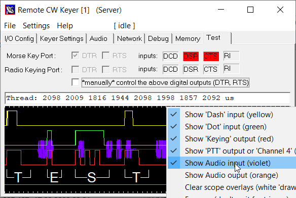
Early version of the 'Remote CW Keyer' application,
with the Timing Scope in action at 35 WPWM.
2.8 The 'Timing Scope'
The Timing Scope is a simple digital oscilloscope, displayed in the lower part
of the 'Test'- and the 'Keyer Settings' tab.
With the default configuration, it shows the following channels (from top to bottom):
- Channel 1, yellow:
- Logic state of the 'dash' input : low = paddle contact open, high = closed.
- Channel 2, green:
- Logic state of the 'dot' input
- Channel 3, red:
- Logic state of the 'CW keying' output : low = 'RF carrier off', high = 'RF carrier on'.
When configured for manual PTT switching
and the key is operated without activating the PTT,
the program only generates a sidetone but won't transmit. In this case, the 'CW keying'
signal is plotted with a lower amplitude to indicate the signal isn't really being sent.
- Channel 4, blue:
- Per default, shows the state of the 'PTT keying' output: low=receive, high=transmit.
The source for this channel (4) can be selected
in the program's main menu under 'Settings' .. 'Connect Scope Channel 4 to ...'.
Channels displayed on the scope can be configured in its context menu.
Right-click into the scope to open it.
That menu also allows to display a certain audio signals
and the audio spectrum from the DSP:
White ticks at the upper and lower edges are the timescale.
Each tick represents a single 'dot interval', depending on the
current setting of the keyer speed in WPM.
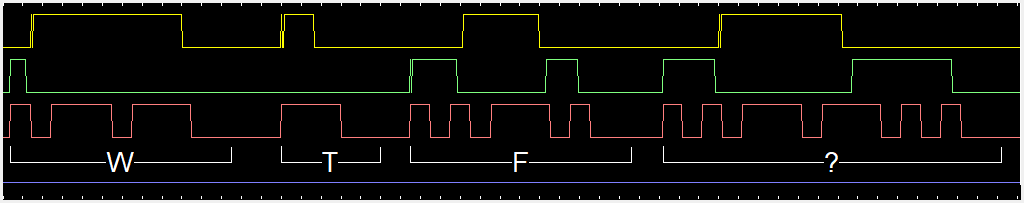
Waveforms displayed on the Timing Scope from a 'single lever' key (w/o squeezing) at 25 WPM.
Note the contact bounce on rising edges (yellow and green trace) from a (t)rusty old key ;o)
If the Morse code signal is generated by the program's built-in
"Elbug" (electronic keyer), and the keyer recognizes a valid
character, it will 'print' the decoded character into the timing scope,
along with an indicator of the character's begin and end.
The built-in decoder recognizes the end of a character by a gap
with a duration of at least two dots (ideal: three dot inter-character space).
A 'word space' is detected when the gap exceeds five dot times (ideal: seven dot inter-word space).
2.8.1 Timing Scope Trigger
The scope display doesn't scroll but sweep ("radar like",
or like an digital oscilloscope in 'slow mode').
The currently updated position is marked by a white vertical 'windscreen wiper'.
When the sweep position reaches the end (on the right), the scope display automatically
pauses until the next trigger event (unless the scope is configured
for 'free running' mode via context menu).
At the present time, a trigger event
is any transition (low to high or high to low) on any of
the scope's input channels.
Upon detection of a trigger event, e.g. operator starting to key again,
the scope shows a few samples before the trigger event. Thus,
when starting to key the next character, the leftmost few milliseconds
visible on the scope show the waveform shortly before the trigger event,
including the rising edge -or the contact bounce- on the dash- or dot input.
It's good fun to see the timing of one's own 'dashes and dots'
on the scope, along with the resulting 'Morse code' (with inter-word spacing),
and to find the personal "speed limit" (when the built-in
decoder sees more garbage than properly spaced characters).
Also, despite the low sampling rate for the digital inputs
(1 / 2 ms = 500 Hz), bouncing electric contacts can often be seen
in the scope waveforms as in the example shown above.
If you spot a wrong character (displayed in the scope or in the
'decoder output' as plain text), simply stop keying. The scope's trigger
will pause at the end of a sweep, and you can see 'what went wrong'
(either with the software, the key/contacts, or the operator's keying, hi).
- Note:
- The timing scope shows the keying signal before travelling
through the Windows 'serial port' API, the USB driver,
and through whatever happens inside the USB<->RS-232
adapter. There's a trick to measure the total delay between
the key (paddle contacts) and the actual 'RF output' (envelope)
of the keyed transmitter, described in the Circuits chapter.
2.8.2 Interactive Readout / Timing Measurements
The scope allows precise time measurements, use the mouse (or touchscreen) as follows:
- Move to the begin of the to-be-measured interval in a Timing Scope trace
- Press the left mouse button (or touch pen), and hold it pressed
- With the left button / pen held down, move towards the end
of the to-be-measured interval.
The program will draw a thin white line between the start- and endpoint.
- At the end of the to-be-measured interval, release the mouse button / pen.
The program will convert the distance along the abscissa (x axis)
into the time difference ("dt" = "delta t") in milliseconds,
and also into the equivalent number of "dot" intervals.
The result will be drawn into the scope screen, near the line
drawn via mouse / touchscreen, as shown in the screenshot:
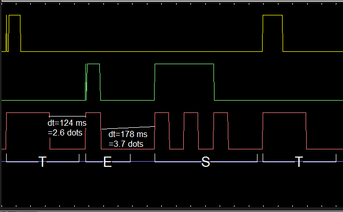
(Click on image to magnify. Note the operator's "poor spacing" between characters:
2.6 "dot intervals" between "T" and "E", but 3.7 dots between "E" and "S".)
- Painting more lines into the scope produces more 'overlays' for readout (up to three,
before the oldest overlay is overwritten).
- To clear all overlays again, select 'Settings' ..
'Clear scope overlays (markers)' in the Remote CW Keyer menu
or in the timing scope's context menu.
- Note:
- Speeds in "WPM" (Words Per Minute) are converted into "milliseconds per dot" as follows:
t_dot_ms = 1200 [ms] / speed_in_WPM
Example: 1200 ms / 22 WPM = 54.54 milliseconds per dot.
For technical reasons (2 ms per thread loop), dashes, dots, and gaps can only be sent
as multiples of 2 milliseconds. Thus the length of the word PARIS,
measured via timing scope from the begin of the first to the end of the last dot,
may not be exactly 43 dot-times, but a few milliseconds more or less.
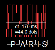
"PARIS" sent remotely at a crazy speed of 300 WPM,
measured with the 'timing scope' on the server side.
Theoretic length = 11(P) + 3 + 5(A) + 3 + 7(R) + 3 + 3(I) + 3 + 5(S) = 43 dots.
With the additional 7-dot word space, PARIS has 50 dot lengths for the "WPM" test.
2.8.3 Sources selectable for the scope's "Channel 4"
Besides the two paddle inputs (channels 1 and 2), and the keyer's CW keying output (channel 3),
the scope's 4th channel can be configured to show one of the following signals:
- PTT switching output
- Only of interest if the 'Radio PTT switching output' is assigned to one of the
digital outputs on the I/O Config tab.
- Test input
- Plots the state of the digital 'Test Input', which can be assigned to one of the
digital inputs on the I/O Config tab.
This feature was used in combination with the 'RF Sniffer'
to measure the total delay between the paddle contacts and the transmitter (or power
amplifier) "keying up".
- Network Trouble Flag
- .. was only used during software development, and will possible be removed in future versions.
- Remote Keying FIFO Usage
- .. was also used during software development and testing, when the CW keying on the
remote server side suffered from drop-outs, caused by network delay and jitter,
or keying commands arriving in 'large blocks' (causing a huge step instead of a
gently rising slope in the Keying FIFO Usage).
- Elbug Keyer Flags
- .. was used to check the proper implementation of keyer modes like Iambic A,
Iambic B, and the 'Basic Iambic Keyer' mode as described by DJ5IL in his
article 'All about Squeeze-Keying'.
The plotted curve is actually a bitwise combination of the "dash"- and "dot"-memories
in the Elbug emulator (Elbug.c):
0 = neither "dash" nor "dot" registered for later transmission,
1 = only a "dash" stored (in what would be a flip-flop in an old ETM key),
2 = only a "dot" stored (in what would be a flip-flop .. " " " ),
3 = both the dash- and dot memories (emulated flip-flops) are SET.
The signals listed above can be selected in the main menu under
Settings .. Connect Scope Channel 4 to ... .
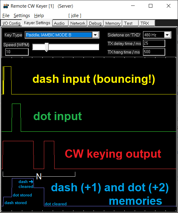
Elbug emulator test with bouncing contact, showing dash- and dot memories
in the blue trace on the bottom ("Scope Channel 4" set to "Elbug Keyer Flags").
The times of clearing dash- and dot memories depend on the Iambic Keyer mode.
2.9 The 'TRX' Tab (Transceiver Control with spectrum display)
If remote control is possible (at the moment, for 'modern' Icom rigs with
Ci-V via USB), this tabsheet shows the most important rig settings (at least the
current VFO frequency and mode), and -maybe- a spectrum / spectrogram.
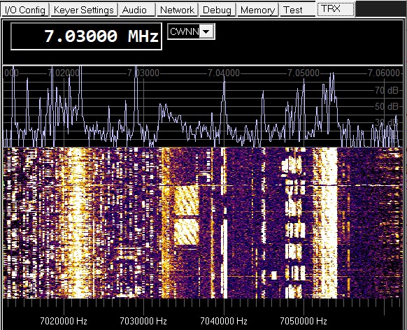
'TRX' tab with a remote display of an IC-7300's spectrum,
with VFO control, S meter,
mode-
and band selector.
Note: For a much more versatile 'remote waterfall display' for Icom radios,
use wfview. The 'Remote CW Keyer' only has this
simplistic spectrum/waterfall display built inside because when it occupies
the radio's CiV-port (via USB), the USB port is occupied, and WFView cannot
access the radio. There's a workaround for this,
but keep that advanced topic for later.
2.9.1 VFO Frequency Control
The 'VFO' field in the upper left corner is a plain text edit field.
The frequency (in MHz) can be typed in directly, but it may be
more convienient to use one of the methods listed further below.
If e.g. an Icom radio is connected via Ci-V (USB, serial port, etc),
the new frequency is immediately sent to the radio.
The program also recognizes if the frequency is modified on the radio itself,
via VFO knob, or from another network user with the permission
to control the remote radio, or from a 3rd-party application via the
optional built-in Hamlib 'rigctld'-compatible server.
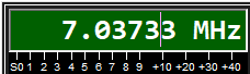
VFO frequency display / input field while changing the frequency.
Note the green background to indicate editing or dragging the frequency.
There are several ways to change the frequency (from within RCW Keyer) - so pick your choice:
To avoid accidentally switching mode or band while you think the mousewheel
or cursor up/down keys control the VFO frequency, the program can automatically
switch the input focus (aka keyboard focus)
back from e.g. the mode/filter control
into the VFO field, after a few seconds of inactivity (no typing, no mouse clicks).
The automatic keyboard focus switch can be disabled in the
Settings menu, for example if you don't need
the mousewheel or cursor keys for VFO control,
or cannot control the transceiver's frequency through RCW Keyer at all.
2.9.2 Transceiver Mode Control (CW,USB,LSB,FM,..)
The next field (right next to the 'VFO') is a combo box indicating
the radio's "mode", like CW (normal bandwidth), CWN (CW "narrow"),
or CWNN (CW "very narrow", which for modern Icom radios is filter 3).
2.9.3 Band selection and 'Band Stacking Registers'
If the Remote CW Keyer application controls a 'modern' Icom radio
like the IC-7300, IC-9700, IC-705 and sufficiently compatible rigs,
the 'band list' in the upper part of the 'TRX' tab not only contains
a list of bands (by wavelengths in meters or centimeters), but also
the most recent three frequencies that have been in use per band.
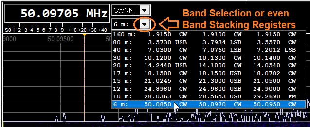
Screenshots with the first experiment to list an IC-7300's "Band Stacking Registers"
in the Remote CW Keyer's Band Selection (combo box). Still missing here:
Entries in the 60- and 4-meter band, available after the 'all band TX' modification.
These 'Band Stacking Registers' (term used by Icom) are read from the
radio when the program starts, or when the built-in rig control module
has reason to assume these registers may have changed.
Each of Icom's band stacking registers not only contains the frequency,
but also the "mode" (modulation type), filter bandwidth, split mode settings,
and even repeater offsets. For details about Band Stacking Registers,
please consult the radio's user manual. Once you get used to them,
you don't want to miss the Band Stacking Registers - and that's
the reason why the Remote CW Keyer supports them.
The content of the band stacking registers is only displayed in short
form (e.g. "3.5605 CW") in the Band selection combo. This is similar
as the Band Stacking Register display in the (Icom-) radio itself,
with an extra digit for 100 Hz resolution. But each band stacking
register stores frequencies with a higher resolution, and contains
more info than just the basic mode. Thus on first glance, there may
be multiple entries for a single band that look the same
(in the combo list, e.g "3.5600 CW, 3.5600 CW, 3.5600 CW") but they
will have different parameters like split mode, audio filter bandwidth,
etc. At the time of this writing, it wasn't perfectly clear when
the radio stores a new "most recent" entry (displayed in the first
column, i.e. 'on top of the stack'), and when it does not.
2.9.3.1 User defined bands and frequencies (in RCWKeyer_Bands.txt)
Instead of reading the supported bands from the rig itself (via Icom CI-V),
the 'sysop' of the remotely controlled station may want to limit the
bands or frequency ranges that the radio may transmit on,
or limit the frequency ranges where the radio (and the antenna!) provides
reasonable reception.
For example, an IC-7300 modified to transmit on 60 meters only reports
a single "TX Frequency Range" (ranging from 100 kHz to 74.8 MHz),
which will exceed the capability of the rig's own power amplifier,
the antenna tuner, and of course the antenna itself.
As the sysop of the remotely controlled station, you don't want anyone,
including yourself, to transmit outside your IARU region's ham radio bands.
User-defined bands are not entered in the RCW-Keyer's GUI, but in a
configuration file that the application loads when starting.
When installed into the recommended directory
(C:\Ham Radio\Remote CW Keyer\Remote_CW_Keyer.exe),
the band configuration will be loaded from file
C:\Ham Radio\Remote CW Keyer\RCWKeyer_Bands.txt .
The self-unpacking installer only places a template file there.
It can be edited with any plain text editor.
In the template file, all entries for the
[Bands] section are commented out (with a semicolon at the
begin of a line). This allows the application
to use all bands that the rig thinks it can transmit on !
Example of the file RCWKeyer_Bands.txt for a hypothetical remote radio site
that can transmit on a few bands,
plus receive on a few extra bands:
[Bands]  ; section with User Defined Bands..
1.81-2.0      mo=CW,LSB tx=0 df=1.8200 dm=CWN
3.50-3.8      mo=CW,LSB tx=1 df=3.5600 dm=CWN
5.3515-5.3665 mo=CW     tx=1 df=5.3525 dm=CWN na="60 m EU" ; transmit here in DL, WRC-15 band
5.2585-5.2640 mo=CW     tx=0 df=5.2600 dm=CWN na="60 m UK" ; receive-only in DL, TX only in UK
7.00-7.2      mo=CW,LSB tx=1 df=7.0300 dm=CWN
10.1-10.13    mo=CW     tx=1 df=10.123 dm=CWN ; CW suggested only between 10.1 and 10.13 MHz
14.0-14.35    mo=CW,USB tx=1 df=14.060 dm=CWN

; Dummy-band to allow RECEPTION on all broadcast bands with e.g. an IC-7300
;  (comment the following line out if you don't want to allow this, as a sysop):
0.1-30.0      mo=ALL    tx=0 df=7.039  dm=CW
In the [Bands] section, there is one line of text per band.
Except for a band's frequency range in Megahertz (from-to),
optional parameters can be specified as key=value pairs.
- mo=
- Operation mode(s) permitted on this band, e.g. CW,LSB,USB.
Multiple values belonging to the same key are separated by comma,
not space characters.
- tx=
- Permission to transmit on this band.
tx=0 means "receive-only", which is the default when not explicitly specified.
- df=
- Default frequency when selecting this band (and no other frequencies
are listed in the same table row, for example from the [Frequencies]
section shown further below.
- dm=
- Default operaing mode when selecting this band (along with "df").
- na=
- Name for the display in the GUI's band selection combo.
Default (when not explicitly specified) is e.g. "80 m" (wavelength in meters).
In addition to the [Bands] section, the file RCWKeyer_Bands.txt may also contain
a [Frequencies] section. The format and optional parameters are similar,
but a line in the [Frequencies] section only describes a "single
frequency of interest", not an entire band or sub-band. Example:
[Frequencies]  ; section with user defined 'single' frequencies :
3.505  mo=CWN  na="80m CW DX"
3.560  mo=CWN  na="80m CW QRP"
7.015  mo=CWN  na="40m CW DX"
7.030  mo=CWN  na="40m CW QRP"
5.3525 mo=CWNN na="60m CW"
10.123 mo=CWN  na="30m CW"
To confirm it has 'loaded' the file with the user-defined frequencies,
the GUI application shows from where the file has been loaded,
and how many band definitions have been loaded on the program's
Debug tab, for example:
Loaded 29 user-defined bands from C:\Ham Radio\Remote CW Keyer\RCWKeyer_Bands.txt .
Last not least, to show the complete list of user defined bands,
either loaded from RCWKeyer_Bands.txt or sent to your RCW Keyer instance
from the remote server, can be inspected as follows:
In the main menu, select
More built-in test (with output on the 'Debug' tab) ...
List User Defined Frequencies on the 'Debug' tab
It is solely the sysop's decision to allow 'tuning across the entire shortwave spectrum'
(in receive-only mode of course), or only listen to a few selected bands.
For that purpose, the Remote CW Keyer instance running 'as server'
(on the remote side) will send the user-defined bands and frequencies
through the TCP/IP connection (not the file itself, only the data)
to every client that joins in. Thus, QSY-ing via up/down key or mousewheel in the
VFO Frequency Control may stop at the 'band edges' defined
by the sysop.
2.9.4 Spectrum Reference Level and other spectrum/spectrogram related controls
Owners of modern Icom radios with built-in spectrum/spectrogram
(aka waterfall) display will be familiar with the 'REF' softkey
to control the level range (offset ranging from -20 to +20 dB).
This control is especially important to see weak signals
(e.g. QRP CW signals) in the spectrogram display. Ideally,
the reference level is set so that the 'noise floor' just starts
to give a dark blue, or almost black display.
Since the Remote CW Keyer can display the Icom radio's "waterfall"
remotely, it's often desirable to also adjust the radio's 'REF'
level remotely. Along with some other spectrum/spectrogram related
settings, the Spectrum Reference Level can be adjusted through the
Remote CW Keyer's context menu for the Spectrum display:
Click into the spectrum displayed on the 'TRX' tab to open a menu
similar to the one shown below:
Context menu opened by clicking into the spectrum,
or via main menu: 'Settings'..'Spectrum Display Settings'.
2.9.5 Spectrum Span (frequency range displayed on the 'Spectrum Scope')
The context menu shown in the previous chapter also allows changing
the bandwidth diplayed on the (Icom-)radio's local display and on the
Remote CW Keyer's "TRX" tab.
Click on the menu item labelled 'Spectrum Span in "Center" modes'.
This opens a list of 'Scope Spans' supported by modern Icom radios
like IC-7300, IC-9700, IC-7610, and IC-705:
+/- 2.5 kHz, +/- 5 kHz, +/- 10 kHz,
+/- 25 kHz, +/- 50 kHz, +/- 100 kHz,
+/- 250 kHz, and +/- 500 kHz.
- Note:
- Picking an entry from the above list has no effect
if the 'Scope' (Icom slang) isn't in 'Center'- but in 'Fixed Edge' mode.
2.9.6 Frequency Markers, Frequency Info, Beacon Display
In addition to the frequency scale, the Spectrum/Spectrogram display tab
can show an additional panel (on the bottom, below the frequency scale)
with..
- Frequency ranges that the sysop allows to transmit on
(imported from the file with user defined bands.
- Special 'frequencies of interest', also imported from that file.
- Entries from EiBi's frequency database of worldwide radio stations,
which not only contains commercial radio stations but also utility stations
frequencies (like the Russian 'squeaky wheel' and 'channel markers'),
and a few amateur radio bulletin frequencies. Some entries were added by
DL4YHF in the modified
Eibi_Frequencies.txt.
That plain text file is contained in the installer, so you don't need to download the database yourself.
- The callsign of an NCDXF/IARU beacon, controlled by special entries
in the modified database (Ebi_Frequencies.txt).
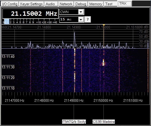
Screenshot of a Spectrogram with the 'bottom panel' indicating the
currently transmitting beacon CS3B (Madeira), shortly after the
stronger signal from OH2B (Finland) appeared on 21.150 MHz.
Note that the callsigns of NCDXF/IARU beacons cycle periodically,
but the display is only correct if the PC's system time is properly set.
The optional 'frequency info' panel, and also the optional 'time markers'
on the spectrogram ("waterfall") can be configured in the
Spectrum Context Menu (right-click
into the spectrum, spectrogram, frequency scale, or frequency info panel
to open that menu).
2.9.7 Chatbox on the bottom of the 'TRX' tab
The optional 'Chatbox' can be used to exchange text messages between sysop and users like..
"Ant: 40 m dipole, Pwr limited to 5 watts",
"Thunderstorm ahead, antenna disconnected",
"QRM from neighbour's solar panels", etc.
When a new message arrives from the sysop,
the chatbox on the bottom of the 'TRX' tab pops up automatically.
Alternatively, it can be opened through the
Context Menu on the TRX / Spectrum screen.
You can respond to message by typing a line of text into the 'Chatbox'. Press ENTER
(with the caret still in 'your' text line) to send it to anyone currently logged in.
Messages sent that way will appear with the sender's callsign in the other user's
chatboxes.
If a sysop has connected to the remote server (using an RCW Keyer instance running
as client, with his secret user name and callsign),
he may use the following tokens on the begin of a single-line text message to let
the remote server interpret the rest of the line as 'something special':
- ann: Sets a new 'announcement' text, shown to all current users,
but also to users logging in later (in future).
2.10 The 'Memory' Tab (with CW transmit memories and macros)
Messages in CW can be sent 'from memory' by pressing a single function key.
This works on any of the keyer's tabsheets, but the Remote CW Keyer must have
the 'keyboard focus' (otherwise Windows won't send keyboard messages to this
application). Message texts can be entered directly on the keyer's 'Memory' tab:
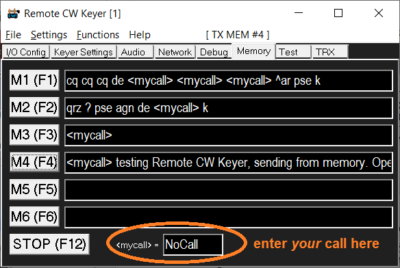
Certain character in the six message memories have a special meaning:
- <macro-name>
- Instead of being sent directly, text between angle brackets
is interpreted as a special command or 'macro'. At the time of this
writing, the following macros were implemented:
- <mycall>
- Inserts (sends) the user's callsign, defined in an edit field
below the six message memories.
- <sNN> (where NN is a two-digit value for the new speed in Words Per Minute)
- Temporarily switches the CW generator to a new speed for transmission.
For example, <s40>5nn</s> switches
to 40 WPM, sends "brrrrt daditt daditt" (the sound of "5NN" at HSCW),
then switches back to the normal speed.
Don't use this outside CW contests
- it's irritating, and not a big 'time saver' if
the receiving station cannot copy what you send
"out of the blue" at high speed.
Actually, this command was implemented for the Winkeyer
emulation, because N1MM Logger+ sends a "buffered speed change"
command in contest reports (customizeable somewhere).
Remote CW Keyer translates that Winkeyer command into the
<sNN> sequence, which the built-in Elbug emulator then
'interprets' while sending the buffered text.
- <s> or </s>
- Switches back to the configured CW speed (shown in the GUI),
that was in use before <sNN>.
Both the short form, and the form inspired by HTML ending tags
(</something> = "end of something") are accepted.
- ^
- Begin of a prosign, in the format specified in chapter
Morse Decoder Output.
Only a few prosigns are actually used in amateur radio, e.g.
^ar = ".-.-." = End of message,
^sk = "...-.-" = "Silent key" (end of traffic from the sender).
Note: For CW contesting, you're better off with a 'contest logger' like
N1MM Logger+, and let N1MM control the Remote CW Keyer as described
here. Sending preconfigured strings and reports from
N1MM Logger does not use the message memories shown above.
Instead, such messages go straight from the "Winkeyer emulator"
to the CW generator.
2.11 Built-in Morse Decoder
The Remote CW Keyer application has a built-in Morse decoder.
This was originally only used to check the own transmission, when sending
with a real Morse key (or paddles) connected to the PC as described
in the introduction.
Later (anno 2025) the CW decoder was drilled up to also decode CW
from the received audio signal.
2.11.1 Morse Decoder Output (-format)
Digits, letters, and other 'normal' characters are printed as plain text.
Prosigns are displayed
in a simular format as used by Icom's built-in memory keyer,
described for an IC-7300 as follows in the 'full' manual,
"Operating CW", "Keyer memory edit menu":
> About the symbols
> * Enter "^" to send a string of characters with no intercharacter space.
> * Put "^" before a text string such as ^AR,
> and the string "ar" is sent with no space.
The same notation must also be used for Prosigns in RCW Keyer's own
transmit message memories.
2.11.2 Decoding CW from the received audio signal
The Audio CW Decoder can be enabled/disabled on the Audio tab.
Per default, it's off (since decoding CW 'by ear and brain'
is more fun than letting a machine decode it). But for a start,
and as a 'backup' (when e.g. the QSO partner ignores "pse QRS"),
it can be turned on as described above, or via context menu
on the 'TRX' tab (right-click into the
spectrum or spectrogram display, select 'More options for the TRX tab'
... 'More options for the Audio CW Decoder ...').
2.12 Installation / Deinstallation
Since the application doesn't depend on any 3rd party tools, no "dot-net"-something
etc, it doesn't need to be installed. But since some users had their
struggle to unzip files and folders from the a zipped archive
after downloading, the Remote CW Keyer can now be downloaded
as a self-installing executable (Remote_CW_Keyer_Setup.exe;
see download link in the introduction).
It doesn't matter where your favourite internet browser has stored
the installer - but at least, you should be able to find
the downloaded file afterwards and start it.
Follow the instructions of the installer, and unless you have a good
reason for changing the destination folder (C:\Ham Radio\Remote CW Keyer),
then leave everything as-is. The installed executable (Remote_CW_Keyer.exe)
needs access to some of the files in the destination folder,
and when placed in the windows "Programs" folder, it may not have
access to its own files (e.g. configuration files, band / frequency
lists, logfiles, recorded audio files, etc).
Newer Windows versions behave a bit paranoid when launching an application
(here: the exe file) that was not downloaded from the
'Microsoft Store'. Depending on the Windows version, something
may pop up with warnings as shown below.
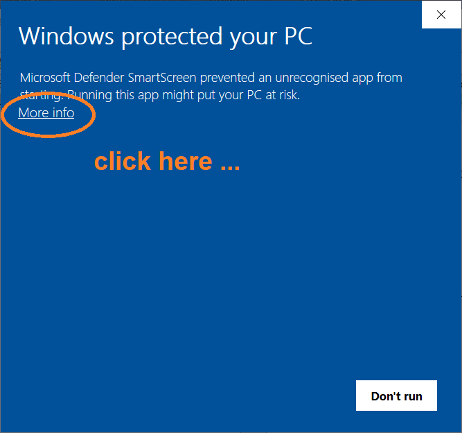
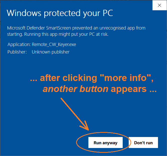
"Windows protected your PC", because the Remote CW Keyer is an "unrecognized app".
Click "More info" to let the hidden button appear, then click "Run anyway".
2.12.1 Installation (details)
Since November 2024, newer versions of the Remote CW Keyer are (only?)
available as a self-unpacking installer.
- If you downloaded an older version of the Remote CW Keyer as an installer-free zip archive (Remote_CW_Keyer.zip):
- Unzip the program (including all files and subdirectories)
into a directory of your choice (not neccessarily "Programme",
"Program File (x86)", "Program Files" or wherever your OS wants you
to 'install' everything).
- If you downloaded a newer version of the Remote CW Keyer as a self-unpacking installer (Remote_CW_Keyer_Setup.exe):
- Try to locate that file in your web browser's "Downloads" folder.
Depending on the browser, you may have to click on "Open File",
or "Show in Folder", etc. In the latter case, double click on
Remote_CW_Keyer_Setup.exe (wherever your browser downloaded it into).
Windows may greet you with a blue screen saying "Windows protected your PC"
again (as already shown in the introduction to this chapter),
but here with "Application: Remote_CW_Keyer_Setup.exe". So again,
click "More Info" to show the hidden button, then "Run anyway".
Also, Windows may greet you with the following (when trying to run
the Inno-Setup-based installer, which may ask for elevated
privileges to create folders or copy files):
User Account Control
  Do you want to allow this app from an
  unknown publisher to make changes to your
  device ?
  Remote_CW_Keyer_Setup.exe

  Publisher: Unknown
  File origin: Hard drive on this computer (or whatever.. "downloaded from the internet" ?)

  Show more details                        (no, thank you very much)

  [ YES ]   [ NO ]
Click yes. Then follow the instructions of the installer
(Select Setup Language, Select Destination Location,..).
If you don't have a good reason for modifying the destination folder,
stick to the default path (which, at the time of this writing,
was "C:\Ham Radio\Remote CW Keyer") - not one of the ever-changing,
user language- and windows-version-specific folders like
"C:\Program Files", "C:\Program Files (x86)", "C:\Programme",
"C:\Programmi", etc. By not installing this software
in the (windows-)'Programs' folder you avoid problems
with non-writeable configuration files in the program's own folder
later - until someone decides to change the rules again.
After that, the directory that you created or selected in the installer
(to let the installer create it) should contain at least this:
   Remote_CW_Keyer
     |--- manual
     |        |-- Remote_CW_Keyer.htm : The manual in HTML format
     |        '-- *.png, *.jpg        : Images loaded by your browser
     |                                  when opening the manual
     |--- sources : The 'most interesing sourcecodes' (written in C).
     |    Since these were only interesting for developers,
     |    the sources have been removed from the executable installer
     |     - see Remote_CW_Keyer_Implementation_Details.htm#Sourcecode .
     |
     '--- Remote_CW_Keyer.exe : This is the executable file .
          Lauch it via double-click, command shell, or create
          a link on the desktop to it (the Inno Setup script
          will have done this, unless you opted out).
When launching Remote_CW_Keyer.exe for the first time, the program
starts with what the author thought are meaningful defaults.
However, the program has no idea about your hardware configuration,
e.g. on which serial port your Paddle / Straight key is connected,
if you plan to control a locally connected radio for testing first,
etc. Thus on the first launch, the program switches to the
I/O Configuration tab where you should select
the 'COM port' numbers, or confirm that you have 'None'.
If you do have a real Morse key, uncheck
☐ use SHIFT and CONTROL key as paddle replacement
because the default (after a 'fresh install') has that option set,
for a quick test (only with a sidetone via default audio device).
2.12.2 Deinstallation
The self-extracting installer (compiled with Inno Setup) will place
a file named 'unins000.exe' in the destination folder with the
executable. Unless you changed the destination folder, the full path
to the uninstaller will be C:\Ham Radio\Remote CW Keyer\unins000.exe .
You can also let Windows uninstall the application via 'Start' menu.
If you don't want to leave any trace on your office PC ;o), the only file
that the program will save on your PC outside the selectable
installation folder is its own configuration, in a
plain, simple, and wonderfully old-fashioned Windows "INI" file
(INI files are simple text files; they can be edited with a plain
text editor if necessary).
Unfortunately, Microsoft/Windows has its own 'ideas' about where to place
such ini files. Placing them in the executables own location would be
too easy, but doesn't work for various reasons.
If you need to know where those files are, see
'Location of the configuration files'
in the next subchapter.
2.12.3 Location of the configuration files
The Remote CW Keyer utility will not touch anything in the Windows 'registry' !
Instead, the program will store its own configuration
in an old-fashioned "ini" file, RemoteCwKeyer.ini .
Ini files are simple text files that can be edited with a plain text editor
like "notepad", and (if you know their location) can easily be copied
from one maching to another, instead of wasting time wading through the
windows Registry.
Unfortunately, the place where Windows stores application's "INI" files
depends on the windows version, the way the program was launched
(which kind of user privileges), the name of the current user,
and possibly the language of the windows installation.
For example, when launched under debugger control from the Borland C++ Builder IDE,
the configuration was saved in
C:\Windows\Remote_CW_Keyer.ini .
When launched with a normal user account (here: user name 'Wolf'),
and without 'admin' privileges, the configuration file was stored at
C:\Users\Wolf\AppData\Local\VirtualStore\Windows\Remote_CW_Keyer.ini .
2.12.4 Automatically running the 'Remote CW Keyer' when starting windows
Like any other windows executable (or "app"), Windows can be configured to automatically
start the Remote CW Keyer shortly after booting the PC. It's easy if you know how,
but unfortunately the way of doing things in Windows differs with each new version.
Many roads lead to Rome, so here's the road the author used (with Windows 10):
- Press the 'Windows' key + 'R' to open a 'Run' box,
and enter the command shell:startup there.
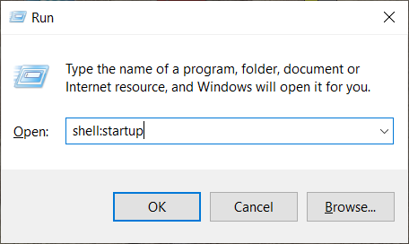
Click 'Ok.
- Depending on your language and the Windows version, a window ("windows file explorer"?)
titled 'Start-up' appears.
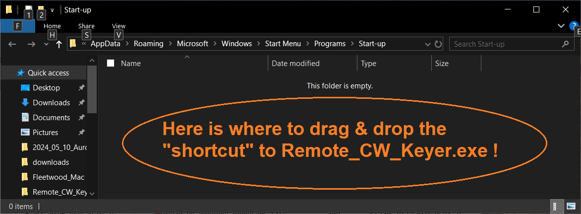
Leave this window open. We will need it in step 4 to drag and drop a freshly created
'shortcut' (something.lnk) into the list of applications to launch when windows starts.
- Use your favourite file manager (which in the author's case is ANYTHING BUT "windows file explorer")
to create a shortcut to Remote_CW_Keyer.exe:
For example, in the author's old-time favourite 'Total Commander', open the folder
into which you have unpacked Remote_CW_Keyer.exe, RIGHT-click that file with the mouse,
and in the context menu (that will hopefully appear in your file manager, too),
select 'Create shortcut':
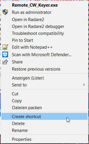
- Grab the freshly created shortcut with the mouse (hold the left button pressed),
then drag and drop it into 'Start-up' thing (or whatever the name
will be, see screenshot from step 2). Let it plunge into the area
showing 'This folder is empty'.
- Note:
- The full name of the 'shortcut file' may be something like
"Remote_CW_Keyer.exe - Shortcut.lnk",
but Microsoft thinks all users are stupid, and won't show you the real file extension
(here: *.lnk) per default.
Not-so-brain-damaged file managers (like Total Commander) will always show
the full file name, and do not foolishly "hide known extensions".
Rant off - after successfully moving the shortcut to Remote_CW_Keyer.exe
into the Windows 'Start-up' thingy, it should show something like this:
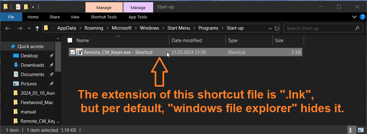
Et voila - with this new entry in the Windows 'Start-up', the PC will automatically launch
the Remote CW Keyer (typically configured as server) when rebooted.
For a 'real' remote operation, server running on a remotely re-bootable
PC far away from home, don't forget to disable the windows Login Screen
aka "Start Screen" / enable "Auto Sign-In". No problem because the remotely
controlled station will be in a locked room anyway, and in case of
burglary / theft, someone messing around with the station's PC (with a user
already signed in) will be your smallest problem.
The simple method of launching the Remote CW Keyer described in this chapter
will not work if windows waits endlessly for a user log-in on the "Start Screen".
There are more laborious methods to work around this (mentioned in the
user's group), but that's beyond the scope of this document.
3. Technical Details, Functional Descriptions, Circuit Diagrams
Note: As this project slowly evolves from a 'proof of concept' into a
real application, some of the contents were moved from this document
into a separate file. Software developers (especially those more
familiar with wfview and Linux..)
may be interested in the protocol details, and in the
'CW keying bytestream format' described in
Remote_CW_Keyer_Implementation_Details.htm#Network_Morse_Routing.
3.1 Methods for remotely keying modern radios
3.1.1 Keying via Ci-V (Icom)
Icom radios like IC-7300, IC-9700, IC-705, and possibly a few others have a built-in keyer
that can translate TEXT (ASCII characters) received via Ci-V (USB/VCP or even LAN or Wireless LAN)
into Morse code. For the author (who prefers rag-chewing in Morse code rather than '599 TU'-style or
Contest QSOs), unacceptable. To send text from a keyboard, we already have WFView
(in 2025, only with a "text input box" or configurable messages to send Morse code remotely).
Theoretically, on the 'client' side, the input from a real Morse key
could be translated into text quite easily before being sent to the radio,
but that's not "the real thing", so this method wasn't evaluated at all.
3.1.2 Keying via USB / Virtual Serial Port
Radios like the IC-7300, IC-9700, IC-705, etc, don't have traditional serial ports but USB
/ "Virtual COM Ports". Besides transporting Icom's Ci-V protocol for
remote control, these interfaces also emulate Modem control signals
(inputs from the radio's point of view), configurable via setup menu
as CW keying signal (IC-7300: "USB SEND / Keying" .. "USB Keying (CW) : DTR"),
and maybe as PTT signal ("USB SEND : RTS") if you don't want to rely on the
radio's internal "semi-break in" feature.
The 'Remote CW Keyer' application (or a similar, yet to be developed add-on for wfview)
can drive at least the CW keying signal as described in a later chapter.
3.1.3 'Audio' keying
Audio keying means e.g. running the remote transmitter in single-sideband (e.g. USB = Upper Side Band),
and feeding in the modulating signal either through the rig's integrated 'USB' (Universal Serial Bus) audio device,
or (for radios with LAN- or WLAN/"WiFi" interface) via Icom's terribly complicated UDP 'audio' port.
Downside: The modulating signal would have to be an 'extremely clean' sinewave, with carefully
shaped ramps. With a typical SSB audio bandwidth of 2.7 kHz, any garbage or artefacts from compression
will cause an excessive transmitted bandwidth, or click spectrum as often heard during CW contests
from totally overdriven power amplifiers. Also, having to switch between 'CW' and 'USB' during each
change-over adds to the software complexity (and makes even Semi-BK operation tricky).
Thus, for a start, this method also wasn't evaluated.
The most common (and universal) method to key a remote transmitter is with
a suitable interface. Such an 'interface' is often just an NPN transistor,
driven by a Modem Control output (e.g. DTR or RTS) on the PC's
serial port / USB<->RS232 - adapter, as shown in the
Circuits chapter.
9-pole sub-D connector for a simple remote keying interface:
| Pin Nr on DE-9, PC side |
Abbreviation |
Normal Function |
Usage (here) |
|---|
| 1 | DCD | Data Carrier Detect | |
| 2 | RXD | Receive Data | Optional Ci-V control (in) |
| 3 | TXD | Transmit Data | Optional Ci-V control (out) |
| 4 | DTR | Data Terminal Ready | Morse keying output
(positive = "key down") |
| 5 | GND | Ground | |
| 6 | DSR | Data Set Ready | |
| 7 | RTS | Request To Send | PTT output
(positive = "transmit") |
| 8 | CTS | Clear To Send | |
| 9 | RI | Ring Indicator | |
Notes:
- The 'PTT' connection is rarely necessary. Let the remotely controlled rig run in 'Semi-BK'
mode, or (if necessary for proper sequencing with e.g. an external PA or RX preamplifier)
use Icom's Ci-V protocol to switch between receive and transmit.
- As long as no application has opened a serial port (and actively controls the "Modem Control" lines
/like DTR and RTS), voltages measured on DTR and RTS ranged from -5 Volts to -12 Volts.
- Due to the network latencies, it's impossible to use the rig's built-in 'electronic' CW keyer.
The Morse code signal, and the indispensable sidetone, must
be generated on the 'client' (operator) side.
Also, having separate 'dash' and 'dot' signals on the server side (radio)
would make things unnecessarly complicated.
3.2 Connecting the Morse key contact(s) on the 'client' side
3.2.1 Polling the Morse key via serial port
9-pole sub-D connector for the 'Simple Paddle Adapter'
(as described later in the Circuits chapter):
| Pin Nr on DE-9, PC side |
Abbreviation |
Normal Function |
Usage (here) |
|---|
| 1 | DCD | Data Carrier Detect | Optional manual PTT switching input
or input from the 'RF Sniffer' |
| 2 | RXD | Receive Data | |
| 3 | TXD | Transmit Data | Optional sidetone output |
| 4 | DTR | Data Terminal Ready | weak 'positive' supply voltage |
| 5 | GND | Ground | |
| 6 | DSR | Data Set Ready | Input from Dash Contact |
| 7 | RTS | Request To Send | weak 'negative' supply voltage
or (rarely used) local CW keying output |
| 8 | CTS | Clear To Send | Input from Dot Contact |
| 9 | RI | Ring Indicator | Another input for various purposes... |
3.2.2 Polling the Morse key via microcontroller
A microcontroller would allow more precise timing (e.g. by timestamping
the digital inputs in bytes sent over the serial port), but for a start,
this method was not tried yet - last not least because the timing
even from the Windows-PC-based 'Remote CW Keyer' software was surprisingly accurate
- see latency- and timing measurements in a later chapter.
Also, lots of microcontroller-based keyer chips with a PC interface
already exit (but only a few support sending timestamped key up/down events
through the SERIAL DATA LINE to the PC; instead they also use the modem
status lines as paddle- or straight key inputs).
3.3 Generation of a low-latency 'sidetone'
If you're into rag-chewing in CW (Morse code) with an electronic keyer (and "bug" keys,
paddles, single-lever or 'Iambic' paddles), you know the importance of a good,
low-latency "sidetone", i.e. a locally generated audio tone that gives an
immediate feedback of the dash, dot or gap currently being sent.
Even with a straight key, a clean, fast sidetone is beneficial.
Any decent radio of today can generate a nice-sounding sidetone,
which is perfect when operated 'locally', but this is usually not
suited when operated remotely (via USB, LAN, or even "the Internet"),
because:
- There's a delay between the paddle contacts and the arrival of
the "dash"- and "dot" inputs in the PC running the client software;
typically a few milliseconds, depending on the USB hardware,
USB driver, and the way the client software 'polls' the signals
from the USB port.
Optimistically (after own experiments documented later),
assume the 'client software' receives the states of the
Morse key contacts via USB (virtual serial port)
with a 5 millisecond delay (t1).
- If the remotely operated radio isn't directly connected to the
'shack PC' but with a network connection in between, the
network latency (in the order of "ping" test times)
must be added twice, because the 'Morse key' state
travels through the network in one direction (from client to
server), and the audio signal (sidetone during transmit)
travels back from server to client.
Assume a "ping" (as in "ICMP" = Internet Control Message Protocol)
travels from client to server and back within 50 milliseconds (t2).
- If, as sound in modern radios, the remotely controlled radio
uses an integrated 'soundcard' (e.g. what appeared as "USB Audio Codec"
from an IC-7300). Thus the sidetone generated 'inside the radio'
travel through several layers of buffering, USB audio drivers, etc.
the latency was as low as for a keyer-generated sidetone.
Assume the audio drivers (including the firmware that drives
the "USB Audio Codec" inside the radio) isn't up to the latest
hype from Microsoft (more on that possibly later), assume
the 'audio delay' on the server side is 20 milliseconds (t3).
- After the 'sidetone' arrives back in the client software,
it needs to travel through some layers of audio buffering again
(application software, driver software, audio hardware),
so expect an audio output latency on the client side of 20 ms,
too (t4).
Summing up the latencies: t1+t2+t3+t4 = ( 5 + 50 + 20 + 20 ) ms = 95 ms.
That's too much by far, so the sidetone must be generated locally.
3.3.1 Sidetone generated by the keyer's microcontroller
Generating the sidetone directly by the keyer is still the best method, because it gives the lowest
possible latency between closing e.g. the paddle's 'dot'- and/or 'dash' contacts. Since the days
of the earliest 'CMOS Keyers' by ETM and others, a sidetone for operating an electronic keyer
("Elbug") could be generated this way, even though they didn't always sound nice (but squeaky, harsh,
unfiltered rectangular waveforms, rich in harmonics).
Adding a sinewave-shaped (low-pass filtered) sidetone from the keyer to the operator's headphones
isn't rocket science, but adds to the cabling mess. Thus, a few alternatives were tried.
3.3.2 Sidetone from the serial port's data output (TXD)
Optionally, a crude (rectangular, 'hard-keyed') sidetone can be taken
from the serial port's TXD signal (serial data output). For this purpose,
the keyer application (described later) configures the "Paddle Interface"
port for 4800 baud, with one start- and one stopbit, and sends an 8-bit data
pattern as long as the keyer shall produce a sideone (during dashes and dots).
Compared with the sidetone from the soundcard, the latency of the sidetone
from TXD was much lower.
With 4800 baud, and 10 bit times per serial frame, this method can generate
a clean 480 Hz tone (abusing the UART's hardware shift register with pattern
0xF0), or (with two 'pulses' in the data pattern 0xCE) a clean 960 Hz tone.
An attempt to generate audio tones around 600 Hz by configuring the serial port
for a non-standard 6000 'baud' speed produced an unpleasant wobbling tone,
so at the time of this writing, only 480 Hz or 960 Hz can be tapped
as sidetone from the serial port.
The Simple Paddle Adapter
circuit shows a simple example for driving a 'piezo speaker' without
active components, directly from the serial port.
The latency achieved by this principle is only a few milliseconds, as documented
here (beween paddle input and 'local' CW on/off keying output,
all on the same COM port).
3.3.3 Low latency audio output from Windows 10 / 11 ?
An article on 'TheWindowsClub' mentioned:
According to Microsoft Low Latency delay is a routine in Windows 11/10,
but it should not be noticeable. Before Windows 11/10, the latency
of the Audio Engine was equal to ~12ms-~6ms, which is now reduced
to 1.3ms for all applications.
Before Windows 11/10, this buffer was always set to ~10ms. Starting with Windows 11/10,
the buffer size is defined by the audio driver. Bingo!
So it's not just Windows responsible, but it is also the driver.
The good news is that Microsoft also says that If an application needs
to use small buffers, then it needs to use the new AudioGraph settings
or the WASAPI IAudioClient3 interface, to do so.
Maybe something to try in future.. at the moment, the program sticks
to the 'mature' audio API (DirectSound), which used to work perfectly
in old Windows versions. If the DirectSound latency is unacceptable,
use one of the other alternatives for the sidetone.
3.4 Network functionality details and troubleshooting
Unlike Icom's complex remote control via LAN/WLAN
(e.g. in the IC-9700 and IC-705) using three UDP ports,
this Remote CW Keyer only uses a simple (single) TCP connection
to avoid having to implement a USB-based protocol (like Icom)
that has to care for automatic retransmission, 'packet counters'
to protect against datagrams arriving out-of-sequence,
and all the stuff you get 'almost for free' when using
TCP/IP instead of UDP.
The price to pay for using TCP is a higher latency,
but even with UDP (used "over the internet"), the latency
was too high for using the radio's own sidetone (remotely)
for electronic keying even at moderate speeds.
Since details are only interesting for developers, but not required
to just use this application, the description of the
Remote CW Keyer's TCP/IP-based client / server protocol
has been moved into a separate document - see:
Remote_CW_Keyer_Implementation_Details.htm .
3.4.1 Network Error Messages (on the 'Debug' tab)
Sometimes, if there is trouble with the network (TCP/IP connection),
socket errors like the following may appear on the keyer window's
'Debug' tab. Here is an incomplete list.
You may find help by asking your friendly search engine, or find details
in the description of the Berkeley Socket API (or the 'Winsock' API by
Microsoft, which is sufficiently similar). The strings were actually
copied from sourcecode module CwNet.c :
- Connection refused
(this often happens if the remote IP address exists, but not the PORT)
- Connection timed out
- Interrupted function call
- Invalid socket descriptor
- Permission denied
- Bad address
- Invalid argument
- Too many open files or sockets
- Call of a WINSOCK function would block
- Operation now in progress
- Operation already in progress
- Socket operation on non-socket
- Destination address required
- Message too long
- Protocol wrong type for socket
- Bad protocol option
- Socket type not supported
- Socket not supported
- Operation not supported
- Protocol family not supported
- Address family not supported by protocol family
- Address already in use
- Cannot assign requested address
- Network is down
- Network is unreachable
- Network dropped connection on reset
- Software caused connection abort
- Connection reset by peer
- No buffer space available
- socket already connected
- Socket is not connected
- Cannot send after socket shutdown
- too many refs
- loop detected
- name too long
- Host is down
- No route to host
- not empty
- Too many processes
- Ran out of user quota
- Ran out of disk quota (funny error for a NETWORK SOCKET...)
- Stale handle reference
- Item is remote
- Graceful shutdown in progress
- Network subsystem is unavailable
- WINSOCK.DLL version out of range
- WSAStartup not yet performed
- Host not found
- Non-authoritative host not found
- non-recoverable error
- valid name but no data
- Other WINSOCK error, code NNNNN (no string entry for code NNNNN)
3.4.2 Network troubleshooting
- Check which (TCP-) ports are in use on the server side, along with the process names
- For this, you will need to open the windows 'Command Prompt' in administrator mode.
This can be done via 'Windows'-key plus 'S', enter 'command' in the search box,
and if you're lucky Windows will offer to run 'Command Prompt' as administator.
In the 'Command Prompt', type
netstat -ab -p tcp
and hit Enter. After some time, the command has finished,
and displays a long list of TCP ports, e.g.:
C:\WINDOWS\system32>netstat -ab -p tcp

Active Connections

  Proto  Local Address          Foreign Address        State
  TCP    0.0.0.0:7355           YHF6:0                 LISTENING
 [Remote_CW_Keyer.exe]  ( <- that's the name of the 'process' that opened the port)
(note that an awful lot of non-important entries has been omitted here)
In a nutshell, the above example from netstat confirms that the Remote CW Keyer
has successfully established a LISTENING port for its
CW Server functionality (on the 'Network' tab).
If, in addition to the 'Remote CW' server, the program shall also emulate
a Hamlib 'Net rigctld' server on e.g. port 4532, that port should
also appear in the long list emitted by 'netstat' on a Windows PC:
Actice Connections

  Proto  Local Address          Foreign Address        State
  TCP    0.0.0.0:4532           YHF6:0                 LISTENING
 [Remote_CW_Keyer.exe]
  TCP    0.0.0.0:7355           YHF6:0                 LISTENING
 [Remote_CW_Keyer.exe]
- Check if RCW Keyer can be accessed in the local network
- This has already been described in chapter 2,
Client/Server test in the local network.
If the local network test doesn't work, but on the server PC
Windows confirms Remote_CW_Keyer.exe is listening on the configured port,
double-check the network settings (may PCs in your local network communicate
with each other at all?), and try to "ping" the SERVER-PC from the CLIENT PC.
To simplify that, when running as server RCW Keyer shows its own
local IP address as explained here.
For example, if the RCWK Server runs on local IP 192.168.178.22, try the following
(in a Windows "command" window, aka console) on a different PC in
the same local network:
C:\Users\YHF>ping 192.168.178.22
Pinging 192.168.178.22 with 32 bytes of data:
Reply from 142.251.211.238: bytes=32 time=5ms TTL=128
Reply from 142.251.211.238: bytes=32 time=6ms TTL=128
  ...
Note: In most cases, you cannot "ping" the remote server via internet,
because the server PC will usually be hidden behind a firewall or similar.
- Check if RCW Keyer can be accessed through the internet
- If you can access the RCW Keyer server in your local network,
but not through the 'public' internet address (URL from a provider like DynDNS, dynv6,
etc etc, or through a fixed IP address if you're lucky to have one), things may get ugly.
Check the following, roughly ordered by complexity:
- Configuring Port Forwarding for the RCWK Server on a 'Fritzbox'
- It happend more than once, after client-server connections "through the
internet" had worked flawlessly for a couple of days, the server could not
be reached through the internet anymore. For example, the author's "Fritzbox" showed...
For this documentation, all old 'Sharings' (Portfreigaben) were deleted
in the Fritzbox.
To define a new 'Sharing' (Portfreigabe) in a Fritzbox, start in the
navigation menu on the left:
"Internet" .. "Permit Access" .. "Port Sharing" ..
- "Add Device for Sharing" (button below the list of Devices / Names)
- "Device" : Select the name of the PC that runs the RCW Keyer SERVER.
- [ ] Permit independent port sharing for this device (leave this UNCHECKED)
- [ ] Open this device completely ... (exposed host) (leave this UNCHECKED)
- Click button "New Sharing" / "Neue Portfreigabe"
- Note the INTERNET-SERVICE-PROVIDER-SPECIFIC,
and EVER-CHANGING range of "Ports Available Externally for IPv4" !
In the author's case, all the ISP had to offer were ports 11116 to 11135 !
- Application: Other application (neither FTP nor HTTP nor HTTPS, etc)
- Name: Remote CW
- Protocol: TCP
- Port to device: 7355 through 7355
(because that's what we used for test in the LOCAL NETWORK; so ymmv..)
- Port requested externally: 11133 (also here: your mileage may vary..)
Chosing anything outside the "Ports Available Externally for IPv4"
caused this field to turn RED in the Fritzboxes user interface.
The 'Fritzbox' seemed to know which port numbers
were 'allowed' by the ISP (Internet Service Provider),
and listed them as shown further above.
So PICK ONE OF THOSE PORTS allowed by your ISP !
- [v] Enable sharing
- (*) Internet access via IPv4 and IPv6
- ( ) Internet access via IPv4
- ( ) Internet access via IPv6
- Click "OK" to apply the above settings.
Back on the "Sharing" tab, the list now showed:
 Status       | Name      | Protocol | IP Address in the Internet | Port Assigned Externally
--------------+-----------+----------+----------------------------+-------------------------
 ( ) grayed.. | Remote CW | TCP      | Click on "Apply" to save.. |  (empty)
Click "Apply" (button way down at the end).
The list under "Port Sharing" still did NOT show a "Port Assigned Externally IPv4" at this point yet !
Wait patiently.. and a minute later, click the "Refresh" button
below the list with columns "Device/Name", "IP Address", "Sharing", etc.
Voila, the display changed to...
Device / Name | IP Address     | Sharing        | Port Assigned   | Port Assigned   | Independent
              |                |                | Externally IPv4 | Externally IPv6 | Port Sharing
--------------+----------------+----------------+-----------------+-----------------+-------------
 YHF6 (PC)    | 192.168.178.22 | (*) Remote CW  | 11133           |                 | [ ] 0 enabled
              |::....:...(IPv6)| (*) Remote CW  |                 | 7355            |
Important: The indicators for 'Sharing' (displayed in the Fritzbox as shown above)
must turn green. If they remain gray, something is wrong.
Despite correct settings on the SERVER side, and on the CLIENT side, and in the
'Fritzbox' (including Port Forwarding and the DynDNS configuration),
it sometimes took minutes until an attempt to connect the SERVER
-via internet- arrived there, as confirmed by Wireshark.
To keep the network bandwidth low (especially for the server, which may
be the bottleneck when streaming audio to multiple clients over a
domestic ADSL line or even via 'mobile internet'),
the audio stream received from the radio (or "soundcard")
is first decimated to 8 kSamples / second. After that,
the low-bandwidth audio stream is passed through an A-Law
encoder. This reduces the sample width from 16 to 8 bits,
resulting in 64000 bits/second (plus some overhead for
the bytestream multiplexing) per logged-in client.
Basically, every 'Morse key up' or 'Morse key down' event is encoded
into a single byte:
  Bits : 7 6 5 4 3 2 1 0
         | |___________|
         |       |
         |    Time to wait between the previous "keying command"
         |    and the emission of the new state in bit 7 .
         |
         '-- H = "key down" (switch carrier ON),
             L = "key up" (switch carrier OFF).

  Encoding of the seven-bit "time to wait" (in bit 6..0) :
    0x00 .. 0x1F :  direct value MILLISECONDS (1 ms resolution)
    0x20 .. 0x3F :  32 +  4 * (value-0x20) ms (4 ms resolution)
    0x40 .. 0x7F : 157 + 16 * (value-0x40) ms (16 ms resolution)
  The maximum time encodable this way is :
                   157 + 16 * (0x7F -0x40) = 1165 ms .
  If an element (e.g. gap or very slow dash) is longer than that,
  multiple bytes with the same state in bit seven are sent.
With only one byte per "key-up" or "key-down" event,
the network bandwidth occupied by the CW keying stream
is almost neglectable.
The original timing (even when sent with a straight key and
a 'personal signature') is preserved.
Like the optional audio signal, the 'CW keying' byte stream is also
multiplexed into the single TCP/IP connection between server and client.
Details about the 'CW keying' stream format are
in the sources - see
Remote_CW_Keyer_Implementation_Details.htm#Sourcecode,
CwStreamEnc.c ("CW Stream Encoder and Decoder").
- Note:
- The PIC18F25J50-based "USB CW Keying Adapter" uses exactly this format over the serial port,
besides signalling the states of the 'dot'- and 'dash'-contacts via emulated CTS and DTR lines.
More about that microcontroller project on the author's
website in future... (2025-11).
3.5 Circuit Diagrams
To operate the 'Remote CW Keyer', only minimalistic hardware is required.
There's no need to invest in any of the well-known microcontroller-based
adapters - neither for the client-, nor for the server side.
The only 'hardware' you need is either a PC with a serial port (unfortunately
out of fashion these days), or an off-the-shelf USB-to-RS232 adapter;
preferrably with an FTDI chip. Stay away from 'Prolific'-based adapters
(with PL2302 chips) due to their habit to 'phase out' support for a
fully functional, but old, hardware in an driver update.
3.5.1 'Simple Paddle Adapter' with sidetone output for the serial port ('client' side)
Suggested DIY adapter between the serial port (or serial port-to-USB-adapter)
and the usual "stereo" 3.5- or 6.3-mm jack compatible with the de-facto
standard ("tip" of the plug = DOT, center ring = DASH), without the need for external power,
and with the Morse key's ground properly connected to the PC's ground:
          --------_                            ,-----------*------*---< DTR (DE-9 pin 4)
  ,-------'        |__   ___   _   _          _|_         _|_     |     (provides a weak
  |  Morse key        | |   | | '-' \        |   |       |   |  __|__    positive supply
  |  plug (male)    __| |___| |_,-,_/        |4.7|       |4.7|  _____    voltage, ca. +5
  '-------,       _|^     ^     ^            | k |       | k |    |1 nF  to +12 Volts,
          --------  |     |     |            |___|       |___|   _|_     software-controlled)
                  Ground Dash  Dot             |           |
                    |     |     |(yellow wire) |           |
                    |     |     '--------------*---------- | --------> CTS (DE-9 pin 8)
                    |     |(green wire)        |           |
                    |     '--------------------------------*---------> DSR (DE-9 pin 6)
                    |                        __|__       __|__
                    |                        _____       _____
                    |(black wire)              | 1 nF      | 1 nF
                    *--------------------------*-----------*---------> GND (DE-9 pin 5)
                   _|_                              (PC ground, mains ground, 'RF ground')
               "Ground" / baseplate of most keys and paddles, should never be 'floating'.
            __
           |                                              |/|
  Optional |                                           ,--|-|--*-----< TXD (DE-9 pin 3)
 "sidetone"|                                  470 nF   |  |\|  |
  output,  |                                        || |       | "denoiser" against
  tapped   |                     ____          ,----||-*       | up to 500 mV pk-pk
  from the |    |\  ,-----------|____|---,    _|_   || |       | voltage ripple on TXD
  paddle   |    | \_|_          1 kOhm   |   |   |_\   |  |\|  | (see notes below)
  adapter  |    | |   |                  |   | _-| /   '--|-|--'
           |    | |___| "Piezo speaker", '---|-  |        |/| 2 * 1N4148 or similar
 (side by  |    | / | headphone adapter,     |___|                silicon diodes
  side with|    |/  |    or similar            |  4.7 ... 10 kOhm
  the key) |       _|_ (see text below)       _|_  potentiometer
           '--                                     for "sidetone volume"
                                                   adjustment (optional)
- Note:
- Compared to other (not recommendable) circuits, where the CW key's
'ground' isn't connected to the serial port's ground (DE-9 pin 5)
but e.g. DTR or RTS, with this adapter, the voltage
on DSR (="dash"-input) and CTS (="dot"- or straight key input)
goes LOW when closing a contact.
When using the recommended circuit shown above, the "polarity"
of the digital inputs (CTS and DSR) can be inverted via software.
So 'invest' in the two pull-up resistors, and maybe three ceramic
capacitors (1 nF each, between the signal lines and gound) for
trouble-free operation, even with "stray RF" in the shack, and
for the bonus of a properly "grounded" base plate on the Morse key.
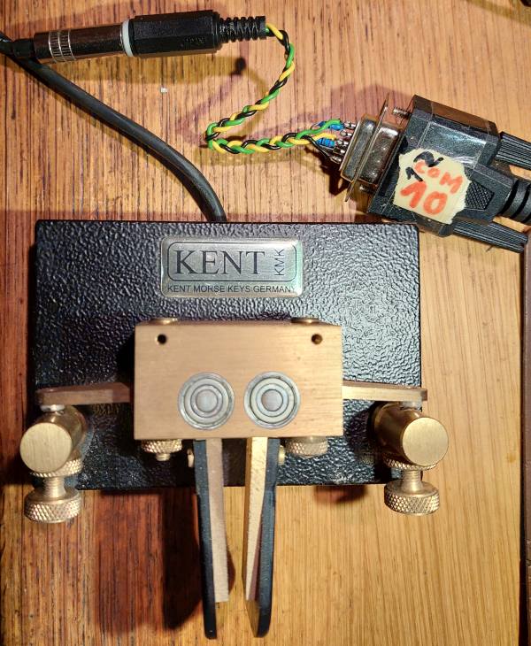
The author's 'Simple Paddle Adapter' prototype, hooked to a Kent key.
Note the "ever-changing COM port numbers" written on the DE-9 plug :o)
Here, the entire 'circuit' are two resistors soldered directly to the DE-9F (female).
Later, an RF Sniffer was added to check the radio frequency keying.
- About the optional sidetone output / "Piezoelectric speaker" driven by TXD:
-
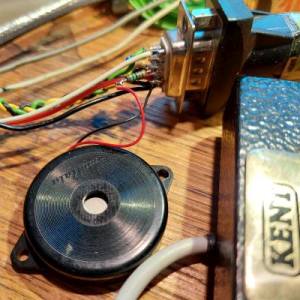 The piezo speaker was a PKM34EW (low-frequency type by Murata),
rescued from the junk. These are high-impedance transducers
without internal electronics (important, because the audio
frequency is generated via software, not inside the 'buzzer' / 'ringer' itself).
Such piezo speakers can be found in smoke detectors,
electronic 'greetings cards' and similar gadgets.
The piezo speaker was a PKM34EW (low-frequency type by Murata),
rescued from the junk. These are high-impedance transducers
without internal electronics (important, because the audio
frequency is generated via software, not inside the 'buzzer' / 'ringer' itself).
Such piezo speakers can be found in smoke detectors,
electronic 'greetings cards' and similar gadgets.
Low-impedance dynamic speakers cannot be used in this ultra-simple circuit
(at least not without a matching transformer) because the serial port
outputs only provide a few milliamps.
An RC low-pass filter, or just a capacitor across the speaker
may be added if the squarewave sound is unpleasant.
"Denoiser" diodes
Due to poor filtering of the +/-12 Volt charge pump driving
RS232 output signals like TXD, some USB <-> serial port adapters
produced a hissing noise on the piezoelectric speaker. This was
caused by 'digital noise' with an amplitude of a few hundred millivolts
(peak to peak). The two anti-parallel diodes in the AC coupled path
cured this, by letting only AC signals above 500 mVpp
pass to the speaker. The AC coupling (470 nF capacitor) also causes
'zero current' from, or into the TXD output when not driven
with a rectangular wave by the software.
One of the adapters with a 'hissing' noise (when used without
the two denoiser diodes) was a
"DIGITUS DA-70156 USB-serial adapter for USB2.0", EAN: 4016032271611.
Besides this minor issue, this FTDI-chip-based adapter was one
of the best in the test, with a low latency also for
the sidetone (when tapped on TXD).
- About the optional manual PTT switching input:
-
Per default, the CW Keyer itself decides when to switch from receive to transmit
and back, so there is no need for an extra PTT switching input (from
the program's point of view).
But for some special applications (i.e. operator wants to use a foot switch to control
the transceiver's, or an external power amplifier remotely), it may be necessary to have
a manually controlled PTT input on the client side. For that purpose,
another input on the serial port (or RS-232-to-USB adapter) can be configured
as input for the PTT. We already use DSR for the Morse key's "dash" input, and
CTS for the "dot" input, so DCD ("Data Carrier Detect") or RI ("Ring Indicator")
remain as a digital inputs to poll the PTT ("Push To Transmit") contact, footswitch, or similar.
See also: Chapter 3.2.1, Polling the Morse key via serial port,
with a list of signals and their pin numbers on the RS232 DE-9 connector.
           To pull-up resistors for   <-------------*--------*---< DTR (DE-9 pin 4)
           dash- and dot contacts                  _|_       |     (provides a weak
           of the Simple Paddle Adapter           |   |    __|__    positive supply)
                                                  |4.7|    _____
                                                  | k |      |1 nF
                                                  |___|     _|_ (RF blocking)
                                                    |
                                                    *--------*---> DCD (DE-9 pin 1)
                                                    |        |
                                                 \  O      __|__
                                        Manual    \        _____
                                        PTT Switch \         |1 nF
                                                    O        | (RF blocking)
                                                    |        |
       GND for the rest of the circuit  <-----------*--------*---> GND (DE-9 pin 5)
      (and the "properly grounded" Morse key)               _|_
On the I/O Config tab, for the simple circuit shown above,
set Manual PTT switching input
to DCD on KEYER port, INVERTED.
See also ('related subject'): Configuration of the PTT switching output on the RADIO port.
3.5.2 RF Sniffer (for a radio / PA keying test with the Timing Scope)
To measure the real total delay between the key (paddle contacts)
and the transmitter "keying up", this primitive RF detector was connected
to one of the unused 'digital inputs' (Modem status lines) on the 'KEYER' port,
in addition to the Simple Paddle Adapter (SPA):
  RF Sniffer (to check TX keying)
                                               ,--------*---------*---< DTR (DE-9 pin 4)
                 /|\  Short wire as           _|_       |         |     (also provides a weak
                / | \  "RF sniffer"          |   |     \|/      __|__    positive supply
                  |   antenna,               |4.7|  to paddle   _____    voltage, ca. +5
                  |   see text .             | k |    adapter     |1 nF  to +12 Volts, for
                  |                          |___|     (SPA)     _|_     the 'paddle adapter')
                __|__                          |
                _____ 27 pF                    *----------------------> DCD (DE-9 pin 1)
                  |                           /  C
                  |  |\|               B    |/
                  *--|-|--*------*----------|        "Dot" from SPA --> CTS (DE-9 pin 8)
                  |  |/|  |     _|_  BC548  |\   E
                -----   __|__  |   |  or     _\|
                 /|\    _____  |1 M| similar   |    "Dash" from SPA --> DSR (DE-9 pin 6)
                /_|_\     |    |___| NPN type  |
                  |       |1 nF  |             |
                  '-------*------*-------------*----------------------> GND (DE-9 pin 5)
      Diodes: 1N5711 or similar                |     (PC ground, mains ground, 'RF ground')
              RF Schotty types, BAT41, ...    _|_
The sniffer is a broadband RF rectifier driving an NPN transistor. The NPN
transistor pulls the 'DCD' (Data Carrier Detect) signal low when it detects...
well, a "carrier" (RF) in the vincinity.
With a 30 cm long "antenna" on the sniffer, a 1 Watt RF signal feeding a shortwave
dipole antenna in a distance of 10 meters was sufficient for detection.
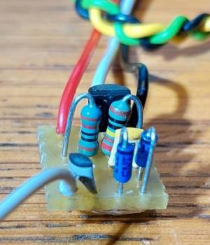
'RF sniffer', temporarily connected to the Simple Paddle Adapter on a serial port
When sending dots at 50 WPM, with the RF Sniffer (DCD signal) selected
as source for the timing scope's 4th channel (blue trace) showed a shorter pulse
at the begin of the transmission, but besides that, they keying seems to be ok
even for high-speed keying via the IC-7300's USB port:
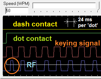
RF "Keying Test" result at 50 WPM, i.e. 24 milliseconds per dot interval.
- Hint for hard- and software testing:
- When entering the speed (in WPM) manually, in the edit field
(without touching the horizontal value slider), the GUI accepts values
way above 50 WPM.
See also: Latency between the paddle inputs and CW modulation (or on/off keyed CW signal
for an external sidetone generator) measured with a real oscilloscope : Only 3.5 milliseconds !
3.5.3 Simple Keying Adapter for the serial port ('remote radio' side)
Unless the transceiver has a built-in USB-to-serial-port adapter suitable for remote CW keying
(like modern Icom radios, e.g. IC-7300, IC-9700, IC-705), or that port is already occupied
by a remote control software like wfview, a simple circuit
like the one shown below can be used to "key" any transceiver:
                     --------_
             ,-------'        |__   ___   _   _   To transceiver's
             |  Morse key        | |   | | '-' \   "Morse key" input,
             |  plug (male)    __| |___| |_,-,_/   configured as
             '-------,       _|^     ^     ^       Straight Key !
                     --------  |     |     |
                             Ground Dash  Dot / Straight Key
                              _|_   (n.c.) |
                                          _|_
                                         |   |
                                         | | | 100 Ohm resistor
                                         | | | or ferrite bead
                                         |___|
                                           |    | | 1 nF for RF blocking
                                           *----| |----,
                                           |    | |    |
                           22 kOhm        /  C        _|_
                            ____     B  |/
    DTR (DE-9 pin 4) >-----|____|--*----|      BC548, BC337, 2N2222,
     or (rarely used)              |    |\     or similar NPN type
    RTS (DE-9 pin 7)               |     _\| E
                       1N4148    -----     |
                         or       /|\      |
                       similar   /_|_\     |
                                   |       |
    GND (DE-9 pin 5) O-------------*-------*
                                          _|_ Ground
Using the same COM port as for the Simple Paddle Adapter, the latency between
paddle input (yellow trace in the o'scope screenshot below) and the
modulation output on DTR (cyan coloured trace) was remarkably low:
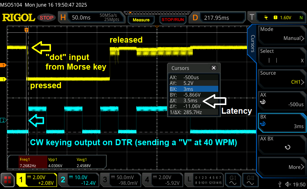
Oscilloscope screenshot with the latency between paddle input and CW output,
with 'Debounce Paddle Inputs' turned off. The Click on image to magnify.
The ripple on the traces (at "H" levels) was caused by the sidetone, tapped from
TXD on the same COM port (supplied by a 'charge pump' in the USB-RS-232
adapter; just a cosmetic issue). This combination results in the lowest possible latency (e.g. 3.5 ms as measured),
because the entire 'keyer emulation' runs in a tight loop ["KeyerThread()"],
executed every two milliseconds. Thus inputs are sampled, and outputs are driven
every 2 ms. With a good USB - RS-232 adapter and driver software (e.g. FTDI),
not much latency is added by those 'extra layers', as confirmed by the screenshot above.
With the option Debounce Paddle Inputs turned on,
the latency between closing the paddle contact and the begin of CW output (and sidetone on TXD)
increased by approximately 10 milliseconds, which is ok except maybe for VHSCW.
Consider this: The speed of sound in air is about 330 meters/second, so a latency of 3.5 ms
is the equivalent of 3.5ms * 330m/s = 1.15 meters between the "sidetone speaker"
and the operator's ears.
3.6 Command Interpreter for 'programmable functions'
... not finished yet ...
In the following lists, only keywords / tokens are underlined.
3.6.1 Tokens to control I/O Ports
These are used for low-level 'programmable functions' to control the keyer,
and to drive digital outputs via I/O lines on Additional COM Ports.
An exclamation mark before the token inverts it, e.g. !CW assigned to RTS emits
an inverted CW keying signal on that pin; !SKEY assigned to RI
reads an inverted straight-keying-signal from the 'Ring Indicator'
(e.g. pin "grounded" when key pressed).
- CW (function assigned to an output pin)
- Emits the 'CW keying signal' (Morse code modulation) on an output pin
(e.g. DTR as in the Simple Keying Adapter).
Intented to drive an external Sidetone generator, or an LED, on any of the otherwise unused
additional COM port outputs, "CW" does not depend on the PTT, and is not affected
by the 'Disable Transmission' status for CW practicing (on the Keyer Settings
tab, in the menu opened via 'More..' button).
- PTT (function assigned to an output pin)
- Emits the 'PTT output signal' on that pin (e.g. on RTS = "Request To Send").
- PTT (function assigned to an input pin)
- Same function as the Manual PTT switching input on the 'I/O Config' tab.
If multiple of these inputs are defined, the program uses a boolean "OR" combination of them.
- DOT (function assigned to an input pin)
- Secondary "dot", aka "dit"-input for the built-in electronic keyer.
Because the threads servicing Additional COM Ports
don't run at the same fast loop interval as the thread for the electronic keyer,
a Morse key / paddle connected to the dedicated 'Dot'-input
configured on the I/O tab will give better timing / less sidetone latency.
- DASH (function assigned to an input pin)
- Secondary "dash", aka "dah"-input for the built-in electronic keyer.
For this freely assignable function, the same restrictions apply as for the "dot"-input.
- SKEY (function assigned to an input pin)
- 'Straight Key Input', active even if the main keyer is configured as 'paddle'.
- TOGGLE (.. the state of an output pin)
- This is an evil command, and should only be used for testing.
It toggles the state of the digital output (e.g. DTR or RTS)
every time the serial port's worker thread runs through the commands
defined in the 'Detailed Settings' dialog
for the Additional COM Ports.
Depending on the CPU speed, the number of cores in the CPU, and the CPU load
caused by other threads and applications, the toggling interval may be anything
from a few to a dozen milliseconds. On the author's PC, DTR could be toggled
(inverted) every 12 ms.
(Technical background: The keyer thread runs in a tight loop,
kicked alive by the Windows "Multimedia Timer" every two milliseconds.
The additional COM port threads usually don't do that,
and thus run slower.)
- RX_ACK (diagnostic function assignable to output pins)
- Produces a short pulse on the output on reception of a byte,
or a block of bytes, on the serial port (RXD).
- TX_ACK (diagnostic function assignable to output pins)
- Produces a short pulse on the output on transmission of a byte,
or a block of bytes, on the serial port (TXD).