Frequency counter with a PIC
|
||||||||||||||||||||||||
This document describes the construction of small frequency
counter with a cheap PIC microcontroller and a few seven-segment LED digits.
The main features of the frequency counter are:
Contents of this document:
The PIC firmware for the frequency counter
can be downloaded from this link (includes
hex file for all display variants and the assembly sourcecode).
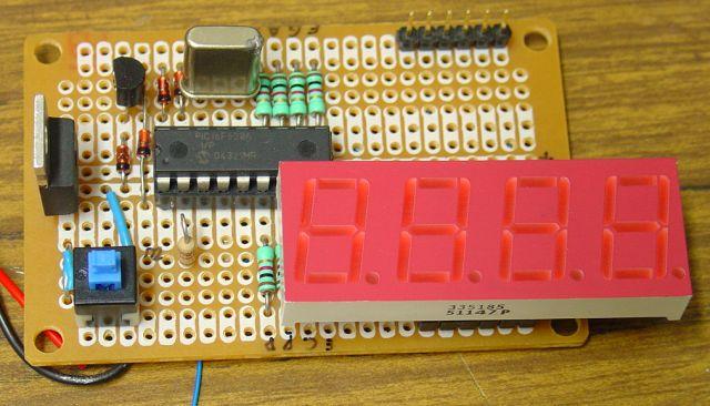
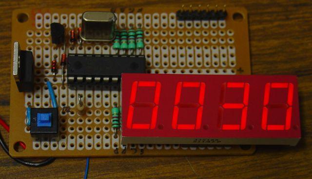
Construction - Variant 1The first prototype with very old, low-efficiency 7-segment displays looked like this:
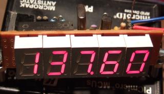
A flashing decimal point indicates a frequency in kilohertz, a steady point indicates a frequency in Megahertz - which is more common for the intended use in dip meters and QRP transceivers. The circuit diagram is so simple that I didn't make a complete Eagle schematic for it yet (other builders did, see links). The first prototype was built on a breadboard with round pads. A very similar design could be used for a single-sided printed circuit board. Four bridges (drawn in red colour below) must be soldered on the board before fitting the seven-segment displays. Note that the crystal is mounted on the bottom side ! Some of the display signal are routed with thin enamelled copper wire, especially those between two pads.
The resistors R4..R11 set the brightness and the power consumption. If you find some suitable low-current displays, use 1 kOhm or even more. Very old displays require more current, use 390 Ohms in that case. The PIC's output ports can source and sink 20 mA per pin, so the digit drivers are a slightly overloaded with 390 Ohm resistors per segment when displaying "8.". If you don't have to care for power consumption and want to use old displays with high current, use four PNP (!) transistors in the cathode(!) drivers as non-inverting emitter followers, no base resistors are required (base to PIC, collector to ground, emitter to common cathode).
For the displays "SC39-11SRWA" by Kingbright it is unnecessary to use driver
transistors, these high-efficiency displaye are bright enough with 1 kOhm
current limiting resistor per segment. In Germany you can -or, at least,
could- order these displays at Reichelt, look for "SC 39-11 RT" in
their catalogue (in fact, these used to be SC39-11SRWA displays; aka "super
bright" / high-efficiency display. Do NOT use the low-efficiency types like
SC39-EWA. You will be disappointed by a dark display, at least with the resistor
values stated above).
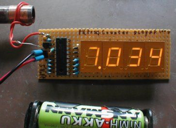
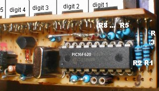
For the second prototype, a 5-digit display was made on a single layer PCB shown below. The segment resistors were used to connect the display board with the PIC board (which is usually mounted in a 90° angle behind the display). To make connection between PIC and display board easier, a second firmware variant was created with slightly modified pin assignment. On this occasion, the PIC's clock frequency was increased to 20 MHz to have a better resolution at higher frequencies.
Schematics of the PIC board (display variant 2)
Component values for variant 2 (as shown above): R1...R8 = 1k, R9=R10=10k, D1..D4=1N4148, T1=BC547 or similar, C1=C2 about 22pF (select them to tune the crystal to exactly 20 MHz), C3=100nF, Q1=20 MHz, PIC: 16F628 programmed with firmware "counter2.hex". Layout of the PIC board (display variant 2). The board contains the decoder for the 5th digit, and some breadboard area for the preamplifier (if needed). Print this image with exactly 300dpi, which can be achieved with IrfanView and other utilities. The image is 700 * 300 pixels large, so the board dimensions will be 2.33 * 1 inch, or 5.93 * 2.54 cm (check this before etching..). The display is mounted on the lower side of the PIC board as shown below. The square pads near the display are the cathode connectors (from left to right: d1..d4 are outputs directly from the PIC, d5 is driven by transistor T1).
Placement of the components on the PIC board (Ridiculously simple, isn't it ? But don't forget to place the bridge under the PIC socket before soldering !).
Here is one suggestion for a layout for the display board (display variant 2, also print this with exactly 300 dpi) :
This board is quite universal, I plan to use it for a PIC-based DDS generator too. For the frequency counter, the connector pads "g","a","f","b" are not used because these four resistors R5..R8 are connected from the PIC board directly to the backside of the first seven-segment digit (see below). The letters on the left side are the segments. The 5 cathodes are not routed to the side of the display PCB - it was impossible with such a small single-layer PCB. Use short pieces of wire to connect the square cathode pads on the display board to the square pads d1...d5 on the PIC board. To save space on the front panel, the connector between PIC- and display-board can be omitted, and resistors R5..R8 on the PIC board soldered to the pins of the leftmost 7-segment display (digit 1). Resistors R1..R4 are soldered to the lower 4 connector pads on the display board. See photo of the second prototype, with the PIC still mounted on a raster board:
Well, using the resistors to connect the CPU board with the display isn't
really nice - feel free to do better (many others did - see links). Common-cathode or common-anode display ? The two display variants (COUNTER1 and COUNTER2) described above are for 7-segment displays with common cathode (CC). But the downloadable software achive also contains a third firmware file (COUNTER3.HEX) for common-anode displays (CA). COUNTER3 uses the same pins as COUNTER2, but the control outputs are inverted. In the circuit, use PNP transistors for the CA display instead of NPN for T1 to drive the 5th digit, furthermore connect D1..D4 with reverse polarity, and connect D4 to Vsupp (positive supply voltage) instead of GND.
With a BF199 in the preamp, R2 is 27 kOhm (+/-), and R3 must be as low as 560 Ohm to achieve the necessary bandwidth. The DC voltage at the collector and the voltage across R3 should almost equal - if not, adjust R2. To save area on the breadboard, you can leave away the preamplifier. If you want to feed the counter with a TTL signal, leave the preamplifier away, which saves another 4 mA. If the maximum frequency in your circuit is below 10 MHz, you may increase the value of R3 and R2 by the same factor (say R3=1.2 k, R2=56k) to save some current when using the counter in a battery-powered device. R1 sets the input impedance and also the sensitivity. With R1=330 Ohm, the prototype required an input voltage of 600 mVpp (peak-to-peak) at 40 MHz and 150 mVpp at 15 MHz. If you need a higher input resistance, add a FET buffer before the bipolar transistor. Or use a fast integrated comparator as input stage if you find one in your junk box. Added 2006-04: You will find a preamp with high input impedance on the pages of the DL-QRP-AG - see links !
Driving the fifth digit (optional)
When all digit multiplexer outputs are passive (digits 1...4 = high), the optional fifth digit is driven. The schematics on the left side show one suggestion for a simple 'decoder' for the fifth digit, which basically is a four-input NAND gate realized with a few diodes, one resistor, and an NPN transistor. The diode between the emitter and ground is used because without it, the transistor may conduct unwantedly if its base-emitter threshold voltage (typically 0.5 to 0.6 V) was less than the forward voltage of the other diodes in this stage (which will be about 0.6 to 0.7 V for a 1N4148). Of course one could use Schottky diodes with lower forward voltages to eliminate the emitter diode, but 1N4148 are more likely to be found in a junkbox than BAT41's (or similar). If you don't need it, leave the 5th digit away to save some current and a few components. For this reason, the 'single zero' (if no input signal is present) is not displayed in the 5th, but in the fourth digit.
The prototype (with R4..R11 = 390 Ohm) drew an average supply current of 40 mA (with 5 low-efficiency digits). With high-efficiency or low-current displays this can be significantly reduced. With 1kOhm segment resistors, the display draws a total current below 20 mA (with 5 digits "SC39-11"). The PIC itself draws about 4 mA at 20 MHz, and less than 1 mA when running at 4 MHz - so the preamp draws more current than the controller itself !
The display range is automatically switched to give the maximum readout accuracy (with 4 digits). The gate time is also selected automatically as listed in the following table:
(On this occasion: "MHz" is Mega-Hertz, "mHz" would be milli-Hertz, but that's
another story...) Adding or subtracting an offset frequency If the counter is used in a shortwave receiver or transceiver, you may want to add or subtract an offset value from the measured frequeny. The offset frequency is the same as the intermediate frequency in many cases, because the counter is usually connected to the receivers VFO (variable frequency oscillator). For this purpose, a programming mode (aka "setup mode") has been implemented in the firmware so you can enter an offset frequency without reprogramming (or even reassembling) the PIC firmware. The signal RA5 (pin 4 of the PIC 16F628) will is used to switch from normal counter mode into programming mode. Usually the level on RA5 is high because it is connected to the supply voltage via pullup resistor (10k to 22k). If you will never need to add or subtract a frequency offset, connect it permanently with the supply voltage (there must be a defined level on RA5, unfortunately it has no internal pullup resistor). By pulling RA5 low (connect pin 4 and pin 5 of the PIC with a small screwdriver), the firmware will be instructed to use the currently measured frequency as the new offset value. In other words, you must apply the offset frequency to the counter's input, wait until the value is displayed correctly, and then enter the programming mode as explained below.
The frequency offset values are saved as a 32-bit integer numbers in the PIC's data EEPROM (at the EEPROM's first four memory locations, high-byte first, low-byte last). If you have no signal generator to produce the offset frequency for programming, or cannot tap the BFO frequency of your homebrew shortware receiver, you can enter the offset value with a suitable PIC programmer (like DL4YHF's WinPic). Use a scientific pocket calculator to convert the frequency (in Hertz, positive or negative) into a hexadecimal number, and enter this value in the PIC programmer's EEPROM DATA memory window. If you use WinPic, enable the HEX editor before typing the values into the memory window. Some examples:
If the subtracted offset is higher than the counter's input frequency, the
result of the subtraction is negative. The frequency counter makes the result
positive before displaying it. This way, you can use the counter also in
receivers where f_IF = f_RX + f_LO, or f_RX = f_IF - f_LO which
means increasing LO frequency means decreasing RX frequency (the counter
will seem to "run backwards" but that's no mistake). Some commonly used IF frequencies can be recalled from the "Table" menu, so you don't have to measure or enter them yourself. In many cases, there is a BFO for the last mixer (at the output of the IF amplifier) which produces a frequency close enough to the desired value.
How it worksBasically the program runs in an endless loop, with the exception of the initial lamp test, programming mode, and power-saving mode which are not explained here. In the main loop the following steps are performed:
Sounds tricky ? Well, you don't have to understand the internal function as long as you don't want to modify the firmware !
Links and other people's frequency counters
The DL-QRP AG use this counter in their "Super Dipper" (an interesting principle
by the way). A description of the dipper -which contains the counter and
preamp schematics- is available online
here. The
frequency counter is on a separate PCB, which is available as a kit from
the DL-QRP-AG, see
www.qrpproject.de/UK/DL4YHFcounter.html
. Later, a second version with smaller display board is available; ideally
suited for small monoband QRP transceivers. Unfortunately the QRP-shop (www.qrp-shop.biz)
closed at the end of 2022, so neither the "Super Dipper" not the digital
counter for Miss Mosquita can be ordered as a kit from their site anymore. My own counter prototype still does a nice job in Miss Mosquita (a neat little QRP transceiver). A short description of the counter in german language is here .
In 2022, Aniello (IU8NQI) ported the PIC assembler sourcecode from the
old MPASM syntax (PIC assembler used with MPLAB, not MPLAB-X) to
Microchip's "pic-as" (assembler used with MPLAB-X, not MPLAB),
and added a new intermediate frequency (10.695 MHz) to the IF table. In 2018, Harry Lythall (SM0VPO) created a new circuit board and simplified variant (without the pushbutton for programmable offsets) for his students. The project is described on Harry's site (on his main site, it's under projects / useful circuits / PIC Freq Counter). The boards for display and CPU are separated for flexibility, and there's a display board for some nice large high-efficiency 14-mm high 7-segment displays.
In 2017, Nigel Kendrick modified the counter firmware to use an oscillator module
rather than a simple crystal. This freed another I/O pin, so the fifth digit
can now be driven without the discrete NAND-gate (transistor with diodes).
The modified sources are available on Nigel's Github repository.
In 2011, Krzysztof (SQ3NQJ), made
Don, KC7ZOW, has more detailed construction notes, and screenshots of the config mode which may help you troubleshooting the display. Erich, VK5HSE, added support for other crystal oscillator frequencies in his firmware variant. In July 2015, his modifications could be downloaded from github.com/erichVK5/DL4YHF-FrequencyCounterVK5Mods, along with Gerber data for a printed circuit board. Lutz (DK3WI) built a portable counter which he describes here (in german language) . Richard (VA3NDO) has some photos of his counter on his website. Like all the others mentioned below, his board looks much cleaner than my prototype ! V. Kocka-Amort made a variant with a divide-by-four prescaler, using 74AC74 high-speed flip-flops, Schmitt-Trigger inputs, and a preamplifier with BFS17A. The circuit diagram, PCB (for Eagle Version 5.9.0 'free edition'), modified firmware, and photos are in this zipped archive. It was tested up to 172 MHz, but may possibly work up to 200 MHz. Lukasz (SQ2DYL) made a nice PCB for the counter, and translated the description into Polish language. His project can be found on this website of the SP-QRP group . Renato (PY2RLM) made his own PCB of the keyer, which is a bit larger than mine but has everything on the board (not using the resistors as 'wires' between CPU and the display. The link to his website is here. Jose Renato (PU2VFW) pointed me to this site with an article in portugese language. It contains a number of photos of the PCB, and the assembed kit. Luciano, PY2BBS, put up his site in 2010 with updated plans - also in portugese language, including Renaud's 6-digit variant (see below). Rahul (VU3WJM) created a new, single-sided PCB for the counter with 5 digits. He kindly made his layout available: You can download the copper tracks, the component overlay (with component values), and the solder stop mask as PDF files from here. (Note: the transistor drives the first digit, not the last one; but I don't have an up-to-date design). Renaud (F8FII) made a modified version of the counter which drives 6 digits, for the expense of the auto-ranging function (it uses the former decimal point output to drive the extra digit; the decimal points on Renaud's display are hard-wired). Description of the modified hardware, and the modified firmware are on F8FII's website. Jaak built this counter, with a more sensitive input amplifier using an NE592 . Jan Panteltjie modified the counter firmware to send the measured frequency through the RS-232 port. Details are on Jan's website. Joe (K3JLS) built a counter for his Century 21 transceiver - see pictures and description on his website . Shig (JA1XRQ) translated the manual, and the construction details, into Japanese. The translated document is available in PDF format on his website. Andrew (ZL2PD) has notes about the updated '5-digit frequency counter and crystal tester' widely sold as a kit from China. He also made a nice 3D printed enclosure for the kit, so check his website at zl2pd.com/xtalchecker.html. Chetan (KG6NFG) built the counter with a single 4-digit module. Here are two pictures of his counter :
... and here how it glows in the dark :o)
'Anonymous clones' of the DL4YHF frequency counter on EbaySince 2016, there seem to be other 'successful builders', selling almost 1:1 reproductions of the 'DL4YHF counter' on Ebay & Co (some with the minor addition of a simple crystal test oscillator). I don't mind doing that, as long as those kits are offered for a fair price (which they were, at least in February and November 2016). But unfortunately all those kit makers / sellers "forgot" to leave a note about the original developer and where they "found" the sourcecode, firmware, and original circuit diagram. If you found this site in a search engine, looking for...
If you have problems with the kits mentioned above: Please don't ask me to help you out, if there is something wrong with the counter (or the firmware), or have trouble getting the cloned kit to work. In some cases, the PICs had been programmed erratically, with non-functional data EEPROM, not being programmed at all, or the kit was delivered with the wrong seven-segment displays. The "Crystal Oscillator / Quarzoszillator Tester Kit" sold on Ebay/Amazon/etc by "Banggood"/"Sainsmart"/"TOOGOO"/etc etc seems to directly expose the PIC's frequency counter input to the 'outside world' without any protection, and without any preamplifier. I can only speculate that some of the "developers" of the various clones didn't read the original article carefully enough (so far, only 'KKmoon' / 'Frequenzmesser Hohe Empfindlichkeit' seems to have realized the importance of the preamplifiers, which not only boosts the input level but also limits the input voltage to a safe level for the PIC). Thus, the following warning may, or may not, apply to the kit you bought for less than 5 Euros: The input level of any signal input to the PIC (microcontroller) may only range from 0 Volts (= ground) to the supply voltage, i.e. 5 Volts. But this is only true if the PIC is really supplied with 5 Volts (I don't know, I never bought any of these kits). If the supply voltage is only 3 or 4 Volts from a battery, but 5 Volts are fed to the PIC's counter input - ZAP ! A body diode conducts, and if the current isn't limited, it causes a Latch-up, in other words: R.I.P. my dear little chip). Anything more negative than 0 Volt, and anything more positive than the PICs supply voltage can instantly kill the chip ! Again, to clarify this: I (Wolfgang "Wolf" Büscher, amateur radio callsign DL4YHF) am not the kit maker or -seller, but the developer of the original circuit, and (more important for the entire project) the firmware that makes the PIC act as an auto-ranging frequency meter.
|
||||||||||||||||||||||||
|
 The
preamplifier consists of a single HF silicon transistor. I used a cheap BF199
from the junk box, it works well up to 30 MHz and with reduced sensitivity
up to 50 MHz. Make the connection from the collector to the PIC counter input
(pin 3 = T0CKI) as short as possible, because every pF of capacitance counts.
The
preamplifier consists of a single HF silicon transistor. I used a cheap BF199
from the junk box, it works well up to 30 MHz and with reduced sensitivity
up to 50 MHz. Make the connection from the collector to the PIC counter input
(pin 3 = T0CKI) as short as possible, because every pF of capacitance counts.
 The
PIC firmware always drives a fifth digit as the least significant digit,
if the measured frequency is above 10 kHz. Because there was no free
output pin available on the PIC 16F628 to drive another digit, a logic
combination from the first four digit multiplexer outputs was used (digits
1 ... 4).
The
PIC firmware always drives a fifth digit as the least significant digit,
if the measured frequency is above 10 kHz. Because there was no free
output pin available on the PIC 16F628 to drive another digit, a logic
combination from the first four digit multiplexer outputs was used (digits
1 ... 4).
 The program flow chart on the left shows how to enter programming
mode, how to select a menu, and how to execute the associated function. To
enter programming mode, press and hold the programming key (or connect pin
4 and 5 of the PIC with a small screwdriver), until the PIC shows "ProG"
on the LED display. Then release the "key". You are now in the first menu
of the programming mode.
The program flow chart on the left shows how to enter programming
mode, how to select a menu, and how to execute the associated function. To
enter programming mode, press and hold the programming key (or connect pin
4 and 5 of the PIC with a small screwdriver), until the PIC shows "ProG"
on the LED display. Then release the "key". You are now in the first menu
of the programming mode.