Old Ham Radio Stuff
by Wolfgang "Wolf" Büscher, DL4YHF |
Main website:
www.qsl.net/dl4yhf This page: old_hamradio_stuff/index.html |
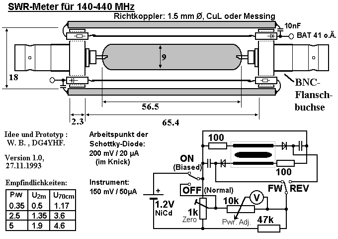
Recently, someone asked me about a VHF SWR meter, which I built over a decade ago from widely available parts. I was lucky to find it in a dark corner of my harddisk, and decided that some of the old drawings may be useful today... so I put them here, on this website, in the hope it may be useful for someone.
Some of the text in the images is in German language. Lengths are given im millimeters if not otherwise stated.

Some notes about this project:
I used a square outer conductor, folded from copper or brass, held in place by the BNC connector (the square-flange type, called "Flanschbuchse" in my German). With a 9-mm brass tube as the center conductor, this gives a good 50 Ohm match. The two reflectormeter lines ("Reflektometer" in german) are 1.5 mm OD enamelled copper. The terminator resistors and schottky diodes are threaded through the former screw holes of the connectors, which just gives the right distance from the surface of the outer connector. The BAT41 diodes can be replaced by something "better" (with less capacitance).
If you want to use a round outer connector, and found some old brass tubes in your junk box, here is a formula to calculates the impedance of a coaxial line, where 'd' is the *outer* diameter of the *inner* tube, and 'D' is the *inner* diameter of the *outer* tube:
Z/ohms = 60 * natural_logarithm( D / d ) ( formula for a ROUND conductors )
Example : 60 * ln (21mm / 9mm) = 50.8 Ohms
For a SQUARE outer conductor (like in the SWR meter shown above), i had found a diagram which suggested a D/d ratio of 2.0 for a 50 Ohm impedance. Here: D = 19 mm (inner diameter of the outer square), and d = 9 mm as outer diameter of the inner tube.
To improve the accuracy at lower power levels, I added a passive circuit to bias the diodes a bit (100..200 mV). This helps especially at power levels from a hand held transceiver (for example when you want to tune your HB9CV antenna at 1 Watt TX power, and the VSWR is already "quite good".
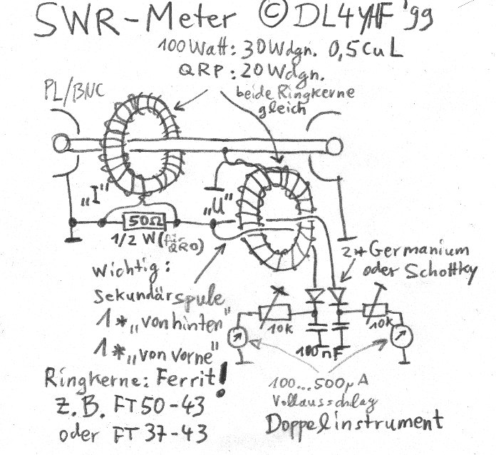
I integrated this circuit in my "Annecke" antenna tuner, using a small stereo level indicator ("Doppelinstrument"). The number of turns on each of the two cores (Ringkerne) must be equal. Both cores are actually used as HF transformers, with a 30:1 or 20:1 ratio. With a high-permeability core, the same circuit also works on 136 kHz. Note the different direction of the wires going through the voltage transformer ("Sekundärspule").

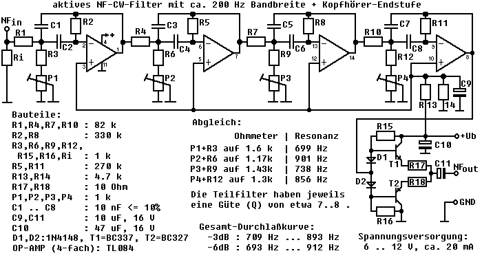
I still use this old filter today, after re-tuning it from 200 Hz bandwidth to about 100 Hz. This can be achived simply by moving the center frequencies of the 4 audio peak filters closer to each other. You don't need a DSP for this..
