Spectrum Lab is more than a simple audio analyser. It has a built-in audio
signal generator with the following features:
This chapter contains:
- Generator function blocks
- Generator control window
- Arbitrary waveform editor
- Generator phase-locking to GPS or timestamps
- Controlling the generator via interpreter commands
- Background notes
The test signal generator can be activated either from Spectrum Lab's main
window or the Component Window: The
output of the generator can be added to the input of the processing chain,
but also to the output (to test external devices). If you need a generator
with I/Q-output, let the signal run through the
FFT-based filter (which can turn normal
signals into complex signals, and remove the "negative" frequencies in the
spectrum if necessary).
See also: circuit window overview ,
main index ,
sample applications .
Generator function blocks
Three independent audio frequencies may be generated WHILE the audio input
of the sound card is analyzed. Each of these "tones" can be adjusted from
0.1 Hz to the half sampling rate in 0.1 Hz steps. By setting a tone's frequency to zero
you turn it off (so you can use this generator also for one-tone- and two-tone-
tests).
The three sine waves are calculated in real-time using the PC's floating
point unit, so you need a fast CPU if you want to generate these tones WHILE
analyzing the input. The generator can be started from the "View/Windows"
menu.
The signal generator also has an adjustable noise generator (white noise).
This is a useful tool for testing filters. You may test the "software"-filters
in SpecLab with this generator, but you can also test a "real" filter with
it if you connect the signal generator to the sound output and the spectrum
analyzer to the sound input.
back to top
Generator Control Window
The signal generator's control window can be opened from Spectrum Lab's main
window, or by clicking on the generator block in the
test circuit diagram.

Here are just some of the generator controls:
-
"Turn On" / "Turn Off":
Used to turn the generator on and off. If you don't need it, turn it off
to save CPU power. If the button is labelled "Turn On" and colored grey,
it means the generator is actually turned off.
-
Sine Wave Generators:
Up to three modulatable sine(+) wave generators can be used in parallel,
each on a different frequency. The following controls exist for every generator.
"On": Used to turn one of the sine generators on or off. If this box is checked,
the generator is active.
"AM": Activates the amplitude modulator for this generator.
"FM": Activates the frequency modulator for this generator.
"Waveform": Select sine, rectangle, triangle or sawtooth here.
"Freq/Hz": You can enter the (center-)frequency of the generator here as
a decimal number (accurate to fractions of a Hertz).
"Frequency Slider": Can also be used to change the frequency rapidly, using
the mouse. Hint: you can also connect the frequency of a generator to a
frequency marker/slider.
"Level": Set the output amplitude of the generator. All three generators
can be individually controlled. The maximum value is "0 dB".
Note: If a suitable GPS receiver is connected to the PC
via soundcard (!),
the output of the sine wave generators can be
phase-locked to the GPS sync
pulse.
-
Noise Generator:
Can be used to add "white gaussian noise" to the common output of the signal
generator. To avoid clipping, keep the noise generators output level below
-40 dB (or even less, if sine waves etc shall be added to the output).
-
Frequency Slider Range:
Affects the frequency range which can be controlled with the three frequency
sliders.
-
Amplitude Modulator:
Define modulation frequency, modulation factor for all "amplitude modulated"
sine wave generators. All three sine generators may share the same AM modulator.
The modulation waveform can be sine, triangle, sawtooth or rectangle.
-
Frequency Modulator:
Define modulation frequency, modulation deviation (peak deviation, "plus/minus
XX Hertz") and the waveform of the modulating signal for all "frequency
modulated" sine wave generators. AM and FM can be combined though this hardly
makes sense. With the frequency modulating waveform set to "sawtooth", the
generator produces a linear sweep which is ideally suited to test audio filters,
or SL's own chirp filter.
-
PTT on:
This checkbox can be used to turn a transmitter on and off, if configured
and wired properly (see configuration
of the PTT control).
-
use table:
Tradeoff between CPU load (caused by calculation of sine waves) and speed.
The default, checkbox 'use table' set, requires less CPU power, at the expense
of spectral purity ("spurious" signals caused by interpolation when using
the sinewave table method are at least 90dB below the carrier, so this shouldn't
be a problem).
If the option 'use table' is unchecked, sinewaves for the generator are
calculated using the processor's floating point unit (FPU), causing an additional
CPU load in the order of 20 percent on a Centrino running at 1.7 GHz clock,
and an audio sample rate of 192 kHz. In that mode, any spurious signals
originating from the sine wave function are at least 150dB below the carrier,
so these sine waves are 'extremely' clean but this is hardly ever required.
back to top
Arbitrary Waveform Generator / Editor
Each of the signal generators -also the AM+FM modulators- can be switched
to "arbitrary waveform" mode. The arbitrary waveform is stored in array with
1024 sample points, from where it can be read out in any desired speed (using
interpolation). To define the waveform, you can ...
-
edit the waveform in graphical form (using "single point" or "line" editing
mode)
-
load the waveform from a short audio file (maximum length is 1024 sample
points).
-
calculate the waveform from a formula - see examples in the table below.
To fill the arbitrary waveform array with calculated values, enter a numeric
formula in the edit field on the right side of the graphic waveform display.
The formula will be evaluated by SpecLab's numeric interpreter.
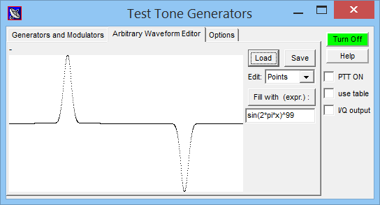
Screenshot of the signal generator's "arbitrary waveform editor",
after filling the waveform array from a numeric expression.
The variable 'x' runs as index from 0 to 1 over the whole array
(regardless of the actual length of the array; so 'x' is the array index
"normalized" to 0 ... 1). To use 'x' in an argument of the trigonometric
functions like sin and cos (sine and cosine), 'x' must be multiplied
with 2 * pi ( pi is a constant, approx. 3.14159265...) .
The result of the formula must be in the range +/- 1 . Some examples :
Expression ("formula") |
Result |
sin(2*pi*x)
|
fills the waveform array with a pure sine wave |
sin(2*pi*x)^3
|
fills the waveform array with a distorted sine wave |
sin(2*pi*x)^99
|
fills the array with a very distorted sine wave |
(x<0.5)
|
fills the array with a pulse, 50 percent duty cycle |
(x<0.1)
|
fills the array with a pulse, 10 percent duty cycle |
(x<0.1)+0.01*((x>0.5)&&(x<0.6)) |
produces a "strong", followed by a "weak" pulse |
(1-x)*sin((5*(1-x))^4) |
"Starwars"-like sound (laser) when played at 5 Hz .
Taken from CrazyBirds1.usr, a nonsense-audio-generator |
rand() |
fills the waveform array with white noise |
back to top
Generator phase-locking to GPS or timestamps
By default, the phases of the generated signals (sine waves, also
for the modulators) are unpredictable - they just start at 'phase zero'
when the generator was turned on, and that's it. Enough for most applications.
Only for a few special cases (mainly testing timestamped audio streams),
it was desirable to lock the test signal generator output to
GPS (with sync output) or a similar
precise source for time and frequency (and thus the ability to measure
"absolute" phases, as specified further below). Alternatively, if there is
no GPS receiver providing timestamps (for the reference phase), the generator's
phase-locking feature can also use UTC timestamps received from
timestamped audio streams.
In any case ("GPS phase lock" or "precisely timestamped streams"), this
option can be enabled on the generator's "Options" tab:
☑ GPS phase lock (or phases locked to timestamps when available)
The above option is actually the same as 'GPS phase lock' on the
Sample Rate Calibrator control panel.
It is only duplicated here for convenience, and because it's also useable without SR calibration.
Controlling the generator via interpreter commands
There are a few commands and functions in Spectrum Lab's
interpreter which can be used to control the signal
generator. They can be used to control the generator from an external program,
etc.
To set a new value, use a formal assignment like
"generator[0].freq=123.4".
The token "generator" can be abbreviated as "gen"
if necessary.
-
generator[N].ampl
-
Reads or sets the amplitude of one of the three function generators (N=0..2)
on a linear scale.
-
generator[N].freq
-
Reads or sets the frequency of one of the three function generators (N=0..2)
in Hertz.
-
generator[N].level
-
Reads or sets the amplitude of one of the three function generators (N=0..2)
on a logarithmic scale, the unit is decibels (dB), 0 dB is the clipping point.
-
generator[N].trigger_cycles
-
Activates the N-th generator channel (N=0..2) for a limited number of output periods of the selected waveform.
Example:
generator[N].trigger_cycles = 1
When configured as square wave output (on the generator control panel),
the above example will emit a single pulse. Intended to be triggered, for example,
by any of Spectrum Lab's programmable buttons,
which may be activated via hotkey (keyboard on the PC) for special tests
- see screenshot of the 'Macro Button Editor' shown further below.
If the assigned value ("number of cycles" aka tone frequency periods) is larger than one,
the command can also be used to send a short tone burst. The duration in seconds would be
the number of cycles (= value assigned to generator[N].trigger_cycles)
divided by the configured tone frequency (= generator[N].freq).
-
generator.on = 1
-
turns the signal generator on (applies to all channels)
-
generator.on = 0
-
turns the entire signal generator off (applies to all channels)
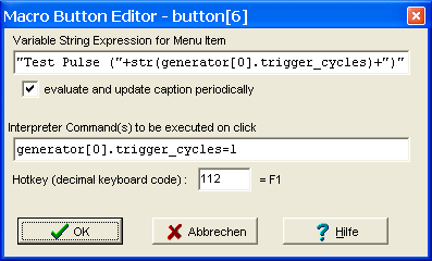
Example: Generator controlled via one of SL's programmable buttons (to send a 'single pulse').
This button is programmed to show the remaining number of 'test pulses' like a countdown.
back to top
Background Notes
The author used this generator to find out how "linear" his "linear transverter"
for 136kHz really was by feeding it with a two-tone signal and analyzing
the transmitted spectrum at the same time. A simple two-tone test is also
good for testing the intermodulation of receivers or single amplifier stages.
It was later used in a 'confidence test' for some of Spectrum Lab's spectrum
analysis functions (using the FM modulator to spread the energy from a sine
generator, without changing the total power).
Tech notes, something to test:
-
Often an FM signal is characterized by the modulation index, which is: mod_index
= peak_deviation / modulation_frequency.
The instantaneous signal frequency sweeps from f_center-deviation to
f_center+deviation.
-
The "carrier" in an FM signal modulated with an index of 2.405, 5.52 and
8.654 disappears completely. This happens for example if the modulation frequency
is 10Hz and the deviation 24.05 Hz. Try it with a sine wave of 1000 Hz, frequency
modulated with a 24.05 Hz sine wave, deviation = 10 Hz : there should be
no signal at 1000.0 Hz .
-
If the signal is modulated with a non-sinusoidal wave (rectangle, triangle,
sawtooth) it is impossible to define a single modulation index - that's the
reason why the FM modulation "strength" is defined as deviation here.
-
Unlike AM, FM does not affect the total power of the signal. Did you already
find out how to validate this with Spectrum Lab ? (tip: check the numerical
analysis functions)
back to top
Last modified : 2020-10-23
Benötigen Sie eine deutsche Übersetzung ? Vielleicht hilft dieser Übersetzer - auch wenn das Resultat z.T. recht "drollig" ausfällt !
Avez-vous besoin d'une traduction en français ? Peut-être que ce traducteur vous aidera !