Homebrew VLF Receiversby Wolfgang Buescher, DL4YHF last updated: January 2011. |
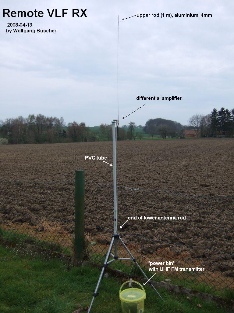
| To escape from the domestic QRM on VLF, a remote E-field
antenna was used. The distance between the RX site and the radio shack was
a bit too large for a cable connection, so a "recycled" UHF FM link is used.
The receiver also runs on battery power to eliminate coupling noise from
the house to the VLF rx site. The dynamic range of this "HiFi" wireless audio
link isn't spectacular, but for occasional listening it's ok (in 2011, it
was replaced with a new FM link).
This is an older (short-range) remote VLF receiver, with the UHF FM transmitter (tiny yagi on top of the yellow plastic bin):
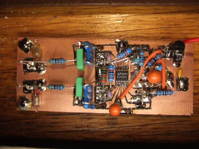
A closeup of the differential amplifier (before an additional L/C lowpass was added). The connector for the upper and lower antenna rod are on the left. A low-noise, large bandwidth opamp (LT 6242) is used as an instrumentation amplifier with very large input impedance. The diagram is similar to the ADA (active differential antenna) described at www.vlf.it .
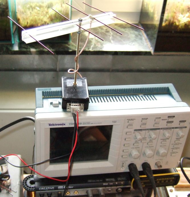
And, in the shack, the UHF FM receiver. It was once a miniature receiver from a wireless "HiFi" headphone, but without the small yagi antenna the received signal was too noisy:
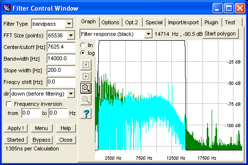
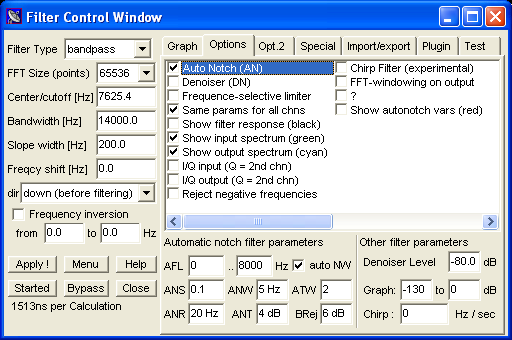
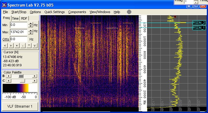
The received signal (from the UHF FM receiver) is fed into an USB audio device (once a Creative Extigy, in the meantime replaced with an EMU-0202 which doesn't require external power). Residual hum is removed from the VLF signal by digital signal processing (automatic multi-notch filter), implemented in Spectrum Lab :
(green curve: input spectrum before filtering with an awful lot of mains
harmonics up to 5 kHz;
For the E-field, the automatic notch filter only needed to operate between 0 and 8000 Hz (parameter "AFL" = autonotch frequency limit). This way, the notch filter does not remove the 'Alpha' beeps around 12 kHz. Besides the limited dynamic range of the FM link, the audio is quite pleasant for occasional listening. Here is a reassigned live spectrogram with a diffuse whistler, some sferics, and the usual 'Alpha' (RSDN) beeps taken 2010-03-22 :
<to be continued..>
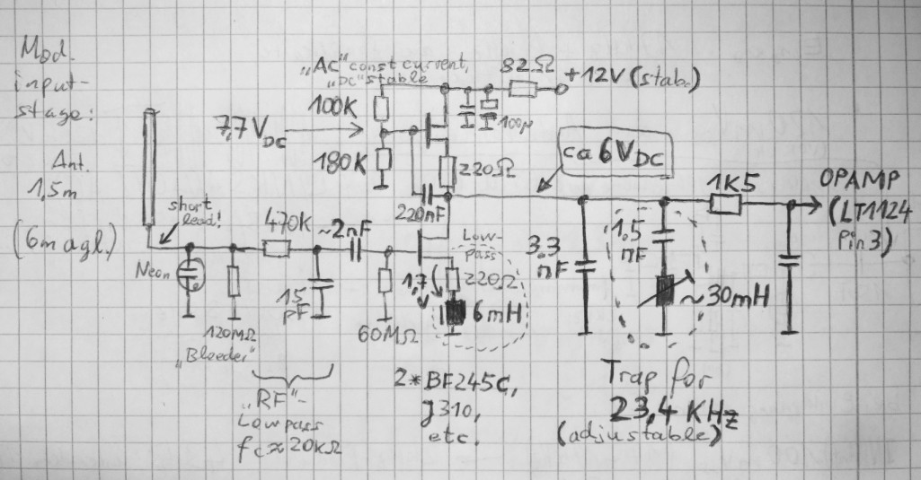
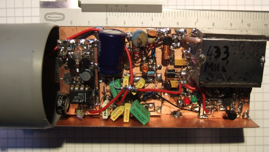
2011-01 : New 'remote' VLF receiverTo get further away from the local QRM (mains), a new E-field receiver was built, this time with a flea-power UHF FM transmitter already inside. In January 2011, this started as a 'platform' to test different frontends, like this one:
Along with other amplifiers and the FM modulator, the VLF 'frontend' was built inside an enclosure to have 'all in a box' (actually, the box is a plastic tube with end caps from the local hardware store). Most sub-circuits are built on individual small breadboards, soldered on the main board, so they can be easily replaced if necessary.
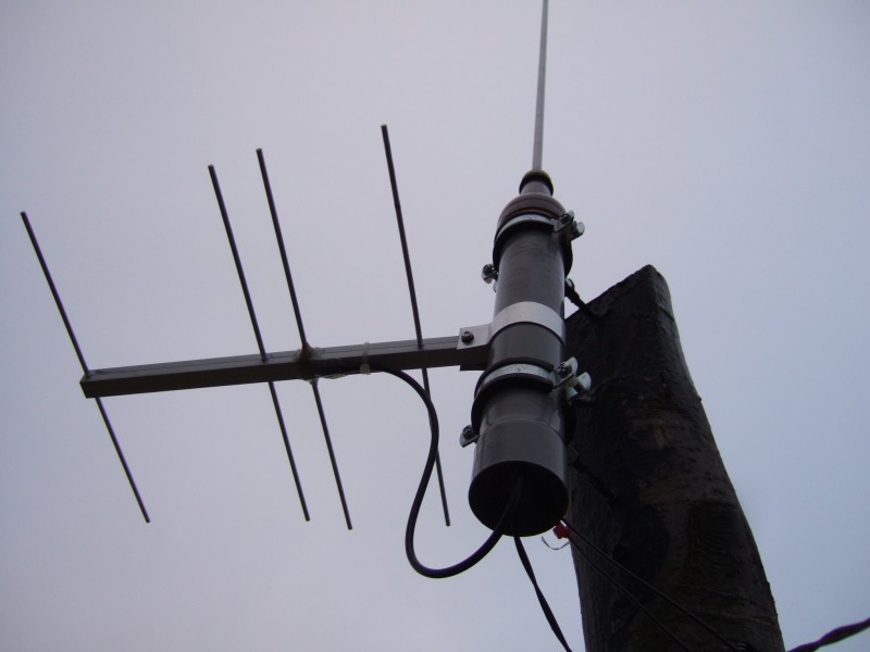
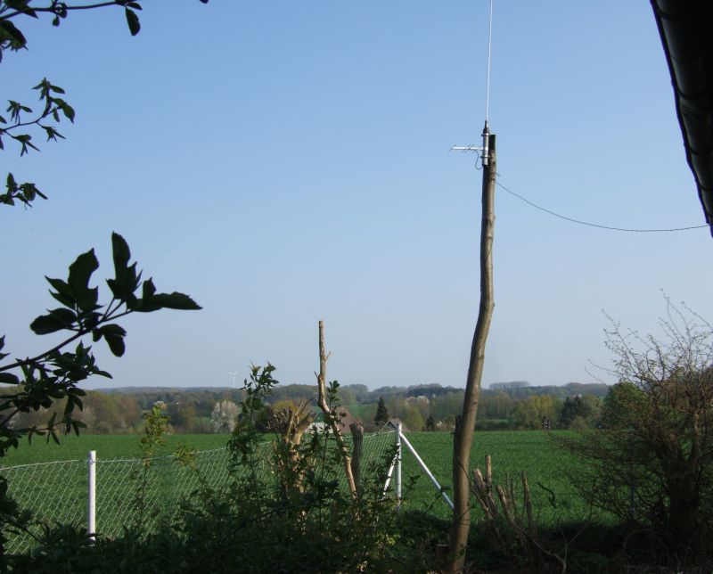
The receiver uses a 1.5 meter long, 1 cm diameter aluminium tube, threaded through one of the plasic endcaps. It is located 6 meters above ground, tied to the trunk of a tree:
The location is pretty rural, but still a lot of noise originating from power lines...
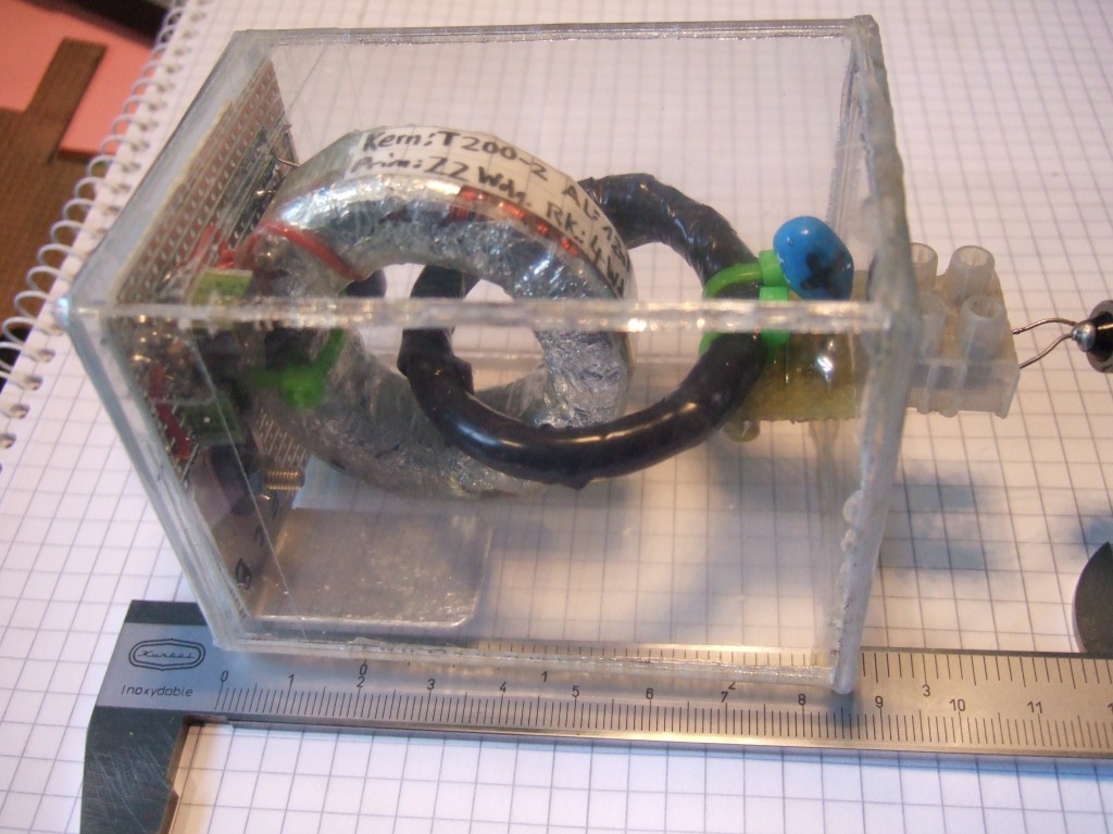
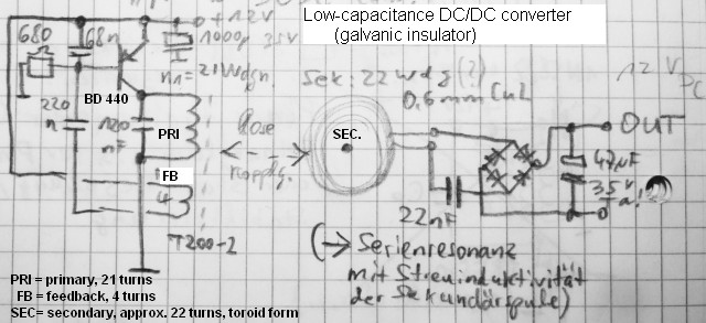
The supply voltage (12 V DC) is fed though a DC/DC converter, which provides galvanic decoupling from the AC mains. This is similar to an 'Austin Transformer' used for lighting radio masts. Actually, this *is* a radio mast even though with an output power of a few milliwatts...
The left side is the input (primary), actually a free running sinewave oscillator running at 200 kHz. The black tape-covered ring is the secondary coil. The small PCB on the right side contains a rectifier, and (added later) a 12 Volt regulator IC for the output voltage, feeding the VLF receiver. Schematics (without the 12 volt regulator on the secondary side, labelled "OUT"). Note that the relatively large stray inductance of the secondary is partially compensated with a series capacitor (here: 22 nF). This capacitor was only required in a test, when the load current exceeded 100 mA. The primary turns are evenly distributed over the T200-2 core. The placement of the 4 feedback turns doesn't matter (but the polarity).
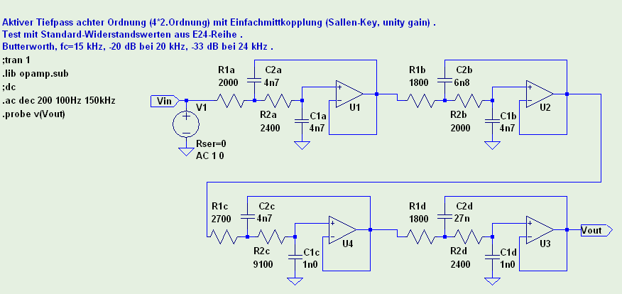
The counterpoise for the VLF receiver is a small ground stake, located as far away from any underground cables as possible. To avoid overloading the FM transmitter with the strong Navy transmitters, an 8-pole 15 kHz lowpass was added between the VLF receiver and the UHF transmitter:
|
See also: Radio Direction Finding on VLF , a ferrite-less, portable VLF H-field antenna , a collection of VLF spectrograms (mostly H-field) , back to DL4YHF's main ham radio homepage
|