Aerials and Feeders (HF)
The following close-
Aerial experiments started with a classic G5RV and a 10W input power transmitter and rapidly moved on to open wire feeders instead of coaxial cable with instant improvements in contact rates and signal reports. To address 1.8MHz, loading coils and extra end sections were initially tried with some improvements over the basic G5RV.
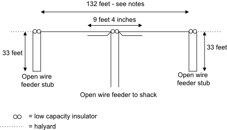
The original idea for the aerial shown above was found in articles in QEX & CQ magazines and has been further developed for the current location. The length of the top started at 132 feet and has been adjusted to obtain a resonance on 1.84MHz with the stubs in place and this will change with aerial height and location -
Results: Worked W/VE/VO on 1.8MHz with 100W CW and Italy on 50MHz with 3W SSB. 1.8 and 3.5MHz are much better than both the original G5RV although directivity is quite pronounced and the radiation angle is quite high -
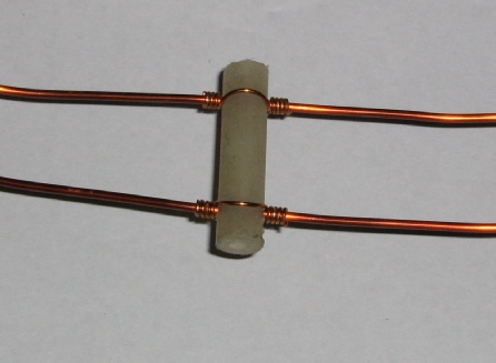
The open wire feeders and the two stubs are made of 16SWG (1/16 inch or 1.6mm diameter) enamelled copper wires spaced 0.90 inch apart with insulators approximately 5 -
The original polythene insulators lasted some 5 years before becoming brittle from UV exposure. They have now been replaced with 8mm diameter acrylic rod insulators which have lasted longer.
A half size version would work well down to 3.5MHz with an overall top length of 66 feet and stubs of 16 feet 6 inches in length. A quarter size with an overall top length of 33 feet and stubs of 8 feet 3 inches should work well down to 7MHz and easily fit into a small suburban garden.
All in all a good multiband aerial. Future ideas for development include alternative traps or stubs and a prototype Z-
However, you will need to do an EMF assessment if each end is close to the ground and therefore people walking by. In my case the ends were about 6 feet above ground and provided a marginal EMF assessment so the aerial was redesigned as shown below to raise the ends further above ground level -
4. Open Wire Feeders
These feeders, used on the above HF aerial, are constructed from 16swg enamelled copper wire for the main conductors, 8mm diameter insulators and 3 inch lengths of 22-
The following photos show the original polythene insulators:

2. Stub Loaded HF Bands Dipole

The following photos show the cutting jig on the left and the drilling jig on the right. Note the removable panel pin in the drilling jig used to hold the insulator when drilling the second hole so that it is parallel to the first hole.

The construction process uses the following steps:
a) Cut insulators to size in the cutting jig and cut two binding wires for each insulator -
b) Smooth each cut end with a file using the cutting jig
c) With the guide pin removed from the drilling jig, drill the first hole -
d) Replace the guide pin, locate the insulator as shown above and drill the second hole. Repeat for all insulators.
e) Acrylic will melt during the drilling process so make sure any build up on the drill is removed otherwise the next insulator will fracture.
f) You may need to clear the drilled holes of any burrs which can be done using a file or rotating cleaned drill bit.
g) Stretch the feeder wires and apply some tension. Avoid any kinks and you can remove or reduce any bends by running the wires through a thick cloth while tensioned.
h) Release the tension, thread the insulators onto the feeder wires and retension.
i) Space the insulators by about 5-
j) On completion, release the tension and coil the feeders prior to installation or use.
5. Weathering
The aerial wire and feeders are virtually impervious to the UK weather although the acrylic feeder spreaders will eventually degrade due to the UV in sunlight and require replacing. Previous polythene spreaders used to last around five years before becoming brittle and breaking -
The loading inductors are more prone to weathering and the current set have lasted about four years before the several layers of external varnish have crumbled to nothing.
The photo below shows a four year old weathered loading coil with failed polyurethane varnish:
3. Inductor Loaded Dipole
An alternative to the stub loading is to use inductor loading which should be fine but the Q of each loading coils is expected to be lower than the Q of the stubs. The initial aerial design is shown in the drawing below and and the calculated inductance for each coil is 85uH and covered in six layers of oil based exterior polyurethane varnish for weatherproofing -

See below for latest revisions.
The resonance on the lowest frequency band will be a function of the length of the centre dipole, inductance of the loading coils, the length of the end sections and their position with respect to nearby buildings, trees and any metal in those buildings. Therefore it will be necessary to erect the aerial, measure the resonant frequency and then make any adjustments required.
The final design after measurements used a 125 foot (38.1m) long top with 83.5uH inductors and 27 foot (8.23m) long end sections. A capacity hat my be used to shorten each end section if required.
The waterproof finish on the inductors should be checked for degradation every year or two and replenished when required. Clean and degrease before adding any new waterproofing. In practice my first set of inductors lasted four years so an alternative waterproof finish will be required -
1. Introduction
I have used open wire feeders on my HF aerials almost from the start of my amateur radio operations because they are almost impervious to weather conditions and exhibit very low losses even when the SWR is high. Narrow spaced open wire feeders are fine for both HF and VHF operation and in the example below have an impedance of around 400ohms.
The following photo shows a replacement loading coil which is longer than the original by 50mm due to the use of thicker wire and more turns to make up the inductance -
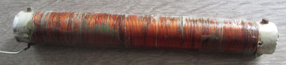

Each end of the plastic former is internally plugged with 25mm long polystyrene rod turned down to be a snug fit and held in place with Araldite (a two pack epoxy adhesive) to increase the overall strength. A 2mm hole is drilled about 15mm in from each end of the plugged tube for the aerial wire to pass through. The solder tag is held in place with a countersunk bolt, surface locking washer and nut which are then varnished.
The pipe is standard 19mm kitchen waste pipe tested in the microwave to check if there is any RF absorption -
Note: Polyurethane varnish is very hard wearing but has poor resistance to the ultra violet (UV) in sunlight. Acrylic varnish is less hard wearing but has much greater resistance to UV and is now my preferred option for external weather proofing. Always do a test of any varnish on inductors in case the varnish permanently lowers the Q (increases the losses) by an excessive amount but wait until the varnish is dry before testing.