LEARNING OBJECTIVES and Notes
|
|
| Capacitance 2 |
|
| Charging a Capacitor |
|
Understand the charging and discharging of a capacitor in a CR circuit and the meaning of the time constant T=CR.
If
a circuit is set up as shown in the drawing, the rate of charge can be
plotted on a graph by taking a reading of voltage across the capacitor
at intervals of time.
When the switch is closed,current starts to flow in the resistor and the capacitor starts to charge.
The formula for the so called time constant is

Where T is in seconds (s), C is in Farads, and R is in ohms.
Lets assume the resistor is 1 ohm and the capacitor is 1 Farad.
Then T=CR
T=1x1
T=1 second
As the graph shows after 1 Time Constant with a 9v battery the capacitor has been charged to 5.7V (63%)
After 2 time constants the charge on the capacitor = 7.8V (86%)
After 3 time constants the charge on the capacitor = 8.6V (95%)
After 4 time constants the charge on the capacitor =8.8V(98%)
After 5 time constants the charge on the capacitor = 8.9V (99%)
Notice that charging slows down with time. This is because as the
capacitor charges up the PD across the resistor is reduced and
this reduces the current flow and the rate of charge.
So, The Time Constant of an RC circuit is the time taken to charge a capacitor to 63% of the supply voltage.
|
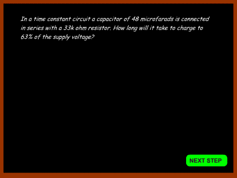
Example 1
Click "next step" to see the stages in the calculations

|
Discharging a Capacitor
This circuit is used to show how a charged capacitor discharges when shorted out via a resistor.
When the switch is closed, current flows through the resistor and the voltage across the capacitor gets smaller.
At first the drop in voltage is rapid because the voltage across the
capacitor is high. As the voltage reduces, the rate of decline
decreases, but by about 5 time constants the voltage across the
capacitor is nearly zero. |
|
|
Recall the dangers of stored charges on large or high voltage capacitors. Recall that large value resistors can be used to provide leakage paths for these stored charges.
•When
a large capacitor is charged up it can hold the charge for a long time.
Touching the positive side, even after the equipment has been turned
off, can lead to a lethal charge.
As a safety precaution,
a high value BLEED RESISTOR is placed across the capacitor. The
bleed resistor allows the charge to slowly leak away without affecting
the operation of the circuit.
Bleed resistors are commonly used in high voltage power where
considerable charges can build up across the smoothing capacitors. |
|
Capacitors in series and in parallel
Understand and apply the formulae for calculating the combined values of capacitors in series and in parallel.
As
resistors can be connected in series and parallel to achieve a different
value, the same applies to capacitors. The formulae are the revers of
those used for resistance.
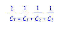
Capacitors in series

Capacitors in parallel

Remember that the formulae
can be used with any number of capacitors. This page happens to show 3,
but for 5 capacitors the formula would be
C total = C1+C2+C3+C4+C5 for capacitors in parallel
|
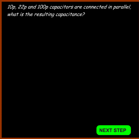
Example 2
Click "next step" to see the stages in the calculations

Example 3
Click "next step" to see the stages in the calculations

|

