
| ADVANCED LESSON 33 |  |
| LEARNING OBJECTIVES and NOTES | |
| Mains Power Supplies | |
|
3p.1 Recall the circuit diagrams and characteristics of different types
of rectifier and smoothing circuits (i.e. half wave, full wave and
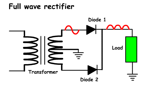
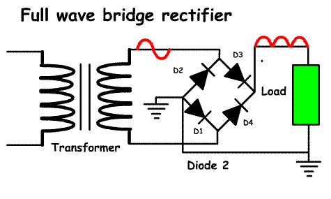
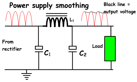
bridge). Mains power supplies are used by most amateurs to convert the mains 230V to either a higher voltage (e.g. for high power amplifiers) or lower voltages(e.g. 13.8 volts for running transceivers) or for variable power supplies for experimental work. Power supplies have three basics stages: 1. a transformer to convert the 230V AC to a lower or higher AC voltage 2. a rectifier to convert the AC to pulses of DC 3. a smoothing circuit to convert the DC pulses into a flat DC output with as little ripple (voltage variation) as possible. 1.Transformers have been covered in Lesson 24 2. Rectifiers There are 3 basic types of rectifier: Half wave rectifiers This consists of a single diode and a load. When the AC voltage from the transformer is applied to the diode, for the positive half of each cycle the diode is forward biased and current flows though the diode, for the negative half cycle the diode is reversed biased and no current flows. The current flows through the load creating a voltage. The drawing opposite shows the input and output waveforms. Full wave rectifier This uses two diodes, a centre-tapped transformer and a load. Bridge rectifiers This uses 4 diodes in a ring structure. A centre-tapped transformer is not required. Smoothing Circuits The output from the rectifier is far from smooth. To smooth the output an electrolytic capacitor of between 2 and 8 microfarads is placed after the rectifier.This charges up to its full capacity as the pulse from the rectifier is going positive, but as it approaches zero volts some of the capacitor charge is absorbed by the load until the next positive going pulse. The effect of this is to prevent the voltage reaching zero. This is then followed by an inductor in series which further smooths the voltage. A second capacitor C2 of 2-8 microfarads. smooths the voltage further to almost a DC voltage with very little voltage ripple on top. |
    |
3p.2 Understand the need for rectifier diodes to have a sufficient peak inverse voltage (PIV) rating and calculate the PIV in diode/capacitor circuits. The maximum reverse voltage that can be applied to a diode is known as the PIV (Peak Inverse Voltage). Beyond this voltage the diode will be destroyed. In a half wave rectifier and a full wave rectifier the PIV is twice the peak voltage. In a bridge rectifier, the PIV is equal to the peak voltage. In practice, diodes are not expensive, so choose one with a PIV and current handling capacity well in excess of what you need. Bridge rectifiers come in blocks with all 4 diodes in one. These should be considered as the PIV is lower than the other two types of rectifier, but look carefully at the output required from the transformer. |
|
| 3p.3
Understand the function of stabilising circuits and identify different
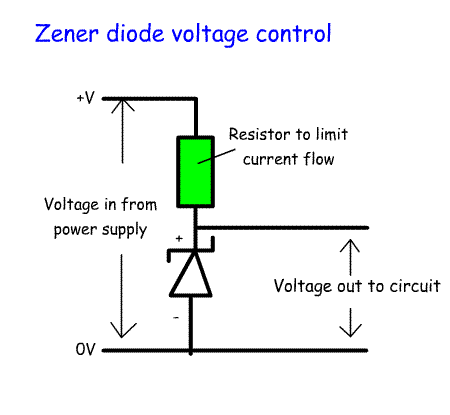
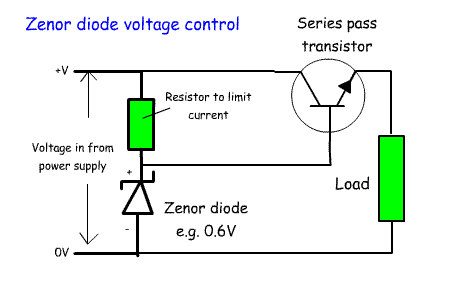
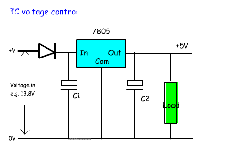
types of stabilising circuits (i.e. Zener diode/pass transistor and IC) Following the smoothing capacitors of a power supply radio amateurs require some form of voltage and current regulation. The voltage regulation ensures that as the current drawn from the power supply varies, the voltage remains constant. It also protects against over voltage. The current regulation ensures that if a piece of equipment tries to draw too much current the power supply will prevent this. Often voltage regulation is built into different parts of the circuit for example VFOs and PA bias circuits use a voltage regulator to provide a stable voltage from the main 12 volt line. We have come across Zener diodes in lesson 30. The value of the zener diode determines the voltage output. These come in many different values. Pass transistors Zener diodes are limited in the amount of current they can carry. By using the output from the Zener diode to control the flow of current through a transistor the voltage will remain regulated, but a higher current will be available. The transistor is called a pass transistor and is configured as an emitter follower. IC voltage regulator These are used widely in modern circuits to regulate the voltage to different parts of a circuit. They look like a plastic transistor. They can be purchased at a fixed voltage and current output or as a variable voltage output. They can be noisy and unstable. This can be reduced by the use of capacitors across the input and output. The 7805 shown in the drawing opposite is used to provide the 5V required by many digital chips from the basic 13.8V power supply. |
   |