| ADVANCED LESSON 40 |  |
| LEARNING OBJECTIVES and NOTES | |
| Transmitter Interference 1 | |
|
4h.1 Recall the effect and the importance of minimising drift. You have seen in previous lessons that careful attention is paid to the stability of frequency generators, particularly VFO's. If these drift, they can cause a number of problems:
|
|
|
4h.2 Recall the cause and effect of ‘chirp’ and identify suitable remedies. Recall the cause and effect of ‘key clicks’ and the shaping of Morse keying waveforms. Causes of chirp Chirp from a CW transmitter is caused by an oscillator that changes frequency slightly every time a dot or a dash is sent. It sounds like a bird chirping. The signal is harder to copy; will interfere with nearby stations and if a narrow band filter is used the signal can move out of the pass band altogether. Remedies for chirp
|
|
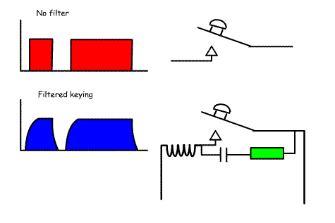
Causes of key clicks These are caused by having dots and dashes with a very fast rise and decay. The effect can be either short distance interference because of radiation from the keying leads, or long distance interference because the square wave from the keyer produces multiple sidebands that can spread over a whole amateur band and even further. Remedies for key clicks
|
 |
|
4h.3 Understand ways to avoid generating harmonics (e.g. use of
push-pull amplifiers, use of inductive coupling between stages,
avoiding high drive levels). Harmonics are multiples of the operating frequency. So, a transmitter on 7.00 MHz will produce harmonics on 2x7=14 MHz (1st Harmonic) 3x7=21 MHz (2nd Harmonic) 4x7=28 MHz (3rd Harmonic) 5x7=35 MHz (4th Harmonic) 6x7=42 MHz (5th Harmonic) If these are not removed they will result in multiple transmissions both within and outside of amateur bands. These can be reduced in a number of ways:
|
|
|
Recall that transmitters may radiate unwanted mixer products and identify suitable remedies. Mixers produce many outputs other than the intended frequency. For example a harmonic of a transmitter VFO frequency could mix with an incoming signal to produce an unwanted frequency. For example a 5.2MHz crystal oscillator might be designed to mix with a 9.0 MHz oscillator to produce an output for transmitter of 14.2MHz (remember 9 + 5.2 =14.2) However, the first harmonic of the 5.2MHz oscillator would = 5.2 x 2 = 10.4MHz. This would mix with a 9.0MHz signal to give 10.4 + 9 = 19.4MHz and 10.4 - 9= 1.4MHz These can get into the amplifier stages and be broadcast. These are not related to the desired frequency and can be above or below the operating frequency. methods of reducing unwanted mixer products: To remove mixer products:
|
|
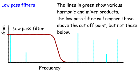
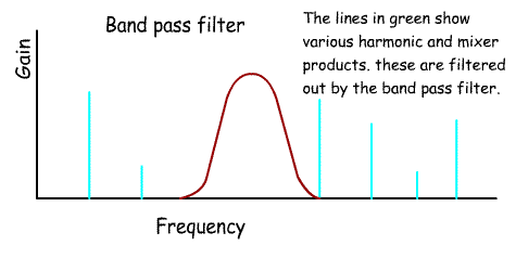
| Understand the use of low and band pass filters in minimising the radiation of unwanted harmonics and mixer products. We have already looked at the design of low and pass band filters to remove unwanted harmonics and unwanted mixer products. The low pass filter will attenuate all frequencies above a certain frequency. These are placed between the PA stage and the antenna output. They will remove harmonics and mixer products above the desired frequency. Band pass filters will remove harmonics and mixer products above the desired frequency and below the desired frequency only allowing through signals in the band pass. On a practical note if you run the output from a transmitter into a dummy load without a filter there will be more power shown than when a filter is used. This is because the filter is removing some RF energy from the harmonics and unwanted mixer products. This is perfectly correct as you do not want to radiate these unwanted signals. |
  |