| ADVANCED LESSON 43 |  |
| LEARNING OBJECTIVES and NOTES | |
| Receiver architecture | |
|
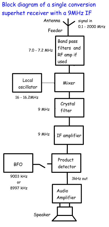
4k.1 Understand the block diagram of superhet and double superhet receivers and the functions of each block. The drawing shows a singleband, single conversion superhet designed for the 7.0 to 7.2MHz band. The incoming signal from the antenna will include signals from a few kHz to several GHz. As we are only interested in signals between 7.0 and 7.2 MHz, we have a front end filter tuned to pass 7.0 to 7.2 MHz. Of course very strong signals could still get through from outside this range. The Band pass filter may be followed by an RF amplifier which is usually used on bands above 20m. There may be another band pass filter following the RF amplifier. Let's assume that we have a 9MHz IF stage, The signal passes into a mixer where it is combined with a local oscillator running from 16 to 16.2 MHz. This will turn all frequencies to 9MHz. We could also have used a local oscillator (VFO) running from 2.0 to 1.8 MHz. This would also turn all frequencies between 7.0 and 7.2 MHz to 9.0 MHz. All the required signals have been converted to 9MHz IF. Turning all signals to a single IF has tremendous advantages over TRF type radios:
The output from the mixer contains the sum and difference of the input frequency and the oscillator frequency. For example a 7.1 MHz signal mixes with a 16.1 MHz to produce an output at 9 MHz and 23.2 MHz. the 9MHz crystal filter selects out the 9MHz signal and passes it on to the IF amplifier. The 7.1 MHz signal has now been converted to a 9MHz signal. The IF amplifier then amplifies this several times. At the end of the IF chain the 9MHz signal is mixed with a BFO signal of 9.003 in a product detector. This is another mixer whose output is at 3 kHz (an audio frequency) which is amplified by the audio amplifier and fed to the speaker. The single superhet has a single mixer and single IF frequency. In superhet receivers the choice of If stage is as follows:
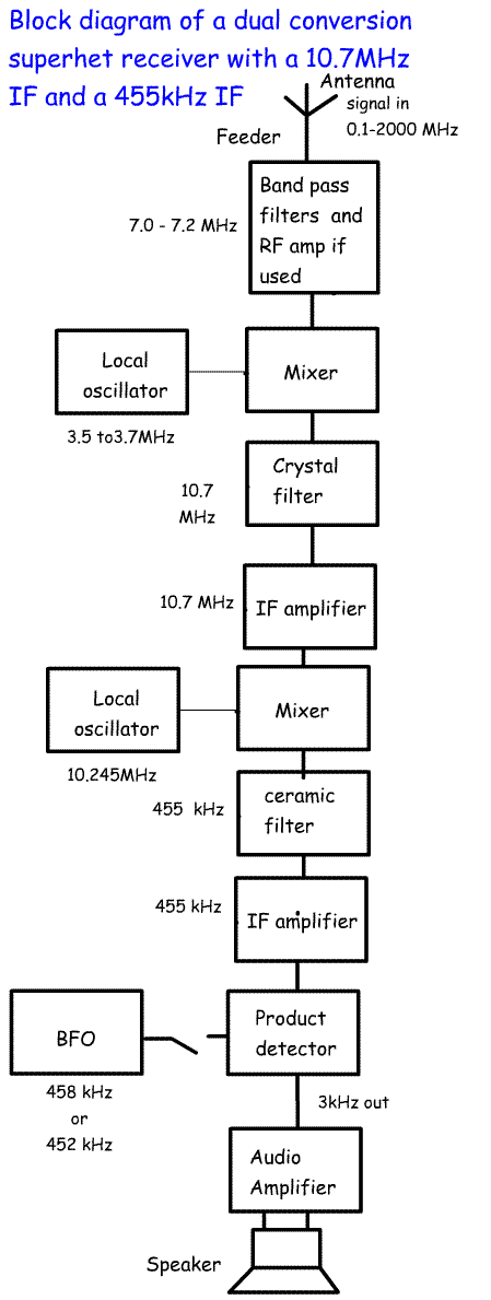
Here is a block diagram of a double superhet with IFs at 10.7MHz and 455kHz. We start as in the single superhet. In this exampl the local oscillator runs at 3.5 to 3.7MHz. When mixed mixed with 7.2 MHz a local oscillator on 3.5 MHz will produce the sum = 10.7MHz. The 7.0MHz signal mixes with 3.7, again to produce 10.7MHz. This is filtered out from the other mixer products by a 10.7MHz crystal filter. This would have a bandwidth of about 2.7kHz for an SSB signal. For a CW station a 10.7MHz filter might be chosen with a 500Hz bandwidth. The IF amplifier is tuned to 10.7MHz and amplifies the signal. This time a second IF is used. A second local oscillator is fixed at 10.245MHz. This is added to the 10.7MHz signal to produce a second IF frequency of 10.700 - 10.245 = 455kHz. This passes through another filter at 0.455kMHz, often made of ceramic material. Because these filters are cheaper often several are used and switched in for a particular mode. So, for NBFM a 12.5 kHz band width might be used. For AM a 6 kHz bandwidth could be used. From the 455kHz filter a second IF amplifier is used. This is tuned to 455kHz. The BFO runs at 458 or 452kHz to produce an audio signal which is fed into an audio amplifier and then a speaker. The fact that the BFO can be switched enables USB and LSB to be received. This is the basis of a high quality superhet receiver. To improve it would require the addition of an S-meter and an AGC system. |
 
|
| R.F. amplifier and pre-amplifier | |
|
4l.1 Recall the operation of the RF amplifier. RF amplifiers are designed to boost the input from the antenna. They are usually placed after the RF filters and before the mixer. With modern mixers an RF amplifier is often not required on the LF bands, but may be useful on the higher HF bands. If the signal is already strong, all they will do is overload the mixer leading to cross modulation. However where a signal is weak they may amplify it, but they need to have a low noise figure. If the noise figure is high then they will do nothing to improve the S/N ratio. |
|
|
Understand that external RF preamplifiers do not always improve overall
performance and will reduce the dynamic range by an amount
approximately equal to the gain of the preamp. The same applies to external RF amplifiers. For example VHF and UHF enthusiasts may have a relay switched RF amplifier at the antenna. Again these need to be low noise. Properly designed and constructed they will overcome some of the losses in the coaxial feeder and may improve the signal to noise ratio. |
|
| Understand that overloading will cause intermodulation and spurious signals. With any pre-amplifier there is a risk that is will overload the mixer and lead to intermodulation and spurious signals. Try turning an RF amplifier on and off while listening to a weak signal Is it clearer? - if so then you have a low noise pre-amp. If the signal sounds the same then you are probably increasing the noise as well as the signal! |