
| ADVANCED LESSON 51 |  |
| LEARNING OBJECTIVES and NOTES | |
| Return Loss and SWR | |
|
5d.1 Understand that the standing wave ratio (SWR) is a measure of the
signal travelling back down the feeder expressed in terms of the
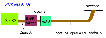
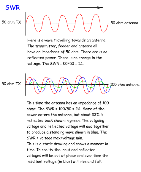
standing waves caused by the reflected signal voltage (or current). One of the first pieces of test equipment amateurs buy is an SWR bridge. This is easy to use. Plug it in next to the TX/RX output and transmit a steady carrier. Adjust the Cal control and read off on the second meter the reflected power. Adjust your Antenna Matching Unit for a signal that shows a minimum reflected power. The diagram opposite shows where to position an SWR meter and an Antenna Matching Unit. What is much harder is understanding what a SWR is. An ideal situation would be where the antenna has an impedance of 50 Ohms. Feeder C has a 50 Ohm impedance and the output from the TX/RX has a 50 Ohm impedance. We can remove the AMU (Antenna matching Unit) as there is no mismatch. The SWR meter will show that all the power is travelling from the TX/RX to the antenna and that no power is been reflected from the antenna to the TX/RX. I.e. the SWR is 1:1. If we were using uninsulated open wire feeder we could measure the voltage anywhere on feeder C and it would show the same voltage. Conditions are never as ideal as this. For example lets assume that the feeder is 50Ohm Coax and the antenna has an impedance of 100 Ohms. Lets assume that there are no losses in the feeder. This time, when the wave reaches the antenna there will be a mismatch. About 66% of the power will be radiated by the antenna and 33% reflected back towards the TX/RX.. Without the AMU, the SWR meter will show a reading of 2:1. The reflected power will then be reflected back from the TX/RX back towards the antenna. If we switch in the AMU and adjust it to match the 50 Ohms to the SWR meter and TX/RX to the impedance presented by the feeder and antenna (This will vary with frequency and length of feeder), the power will be reflected from the AMU back to the antenna rather than been reflected from the TX/RX. The transmitter will "see" a 50 Ohm load. If we were able to measure the voltage along feeder C we would now find that it varied and the maximum and minimum were at points one quarter wavelength apart.. This is because there is a standing wave on the feeder. This will be a sine wave with a maximum and minimum voltage created by the addition and subtraction of the outgoing wave and the reflected wave. In the days when there was only open wire feeder the SWR could be calculated from this formula:  High VSWRs result in a loss of power particularly on coax. The aim is to have a VSWR of 1:1. Many modern transistor PAs are designed to start to reduce power when the VSWR exceeds 2:1. This helps to protect transistors from damage. A VSWR of 1.2:1 or better is considered an excellent value. With the increased use of coaxial cable measuring voltage on the line was not possible and so directional couplers were introduced to measure forward and reverse power. Another point is that other than automatically reducing the transmitter output in modern rigs, reflected power is not lost. It just goes back towards the antenna from the TX/RX and eventually is radiated. the real issue is not the SWR, but the amount of power lost as heat. In open wire feeder losses are very small and so high SWRs on feeder C can be tolerated. This is why amateurs using doublet antennas feed them with open wire feeder. Coax provides much more of a problem as it has a higher loss and so high SWRs lead to more power been turned to heat rather than radio waves! |
  |
5d.2 Recall that return loss is the ratio of the forward signal power to the return signal power; normally expressed in dB. Understand that a low SWR equates to a high return loss and a high SWR equates to a low return loss. A common measurement used to check on the matching between a transmitter and an antenna is called return loss. The return loss is often expressed in dBs and as a negative number. It is important to grasp the fact that return loss is the opposite of SWR. I.e. a high SWR is equal to a low return loss and a low SWR is equal to a high return loss. A return loss of 10dB, means that 1/10 of the forward power is reflected back. Return Loss can be calculated using the following formula:  A low SWR is equal to a high return loss A high SWR is equal to a low return loss NB on some Internet sites and text books you will see the return loss formula as return Loss = 10xLog10(incident power / reflected power) If you used this formula the number of dBs will be the same, but the number will be positive. For the Advanced Exam use the formula given in the syllabus which will give you a negative number! |
|
|
5d.3 Understand that the loss in the feeder will reduce the SWR and
increase the return loss as measured at the transmitter and that the
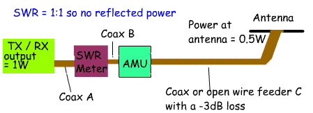
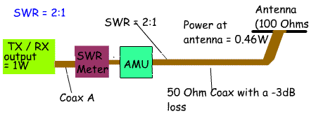
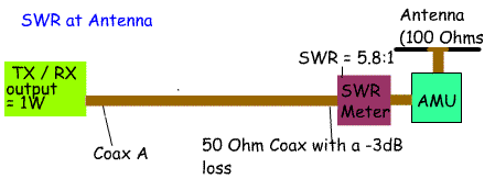
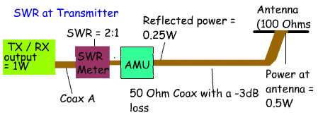
SWR at the antenna is unaffected. Recall that Return Loss at transmitter = Return Loss at antenna + 2×(feeder loss) So far we have assumed that the transmission line is lossless. This is not of course the case. Lets imagine a 1 W transmitter sending power along a length of 50 ohm feed line with a loss of -3dBs to a 50 ohm antenna. Everything matches, so the SWR = 1:1, but because there is a -3dB loss only 0.5 watts will reach the antenna, the other 0.5 watts is lost as heat. Now lets change the impedance of the antenna to 100 ohms making an SWR of 100/50 = 2:1. This time the loss will be -0.35dB + (-3dB) for the feeder loss = -3.35dB = 0.46 Watts. So, the loss in the feeder is much more important than the loss due to a 2:1 SWR. AT a 3:1 SWR the power transferred to the antenna is still 0.41 Watts. If a long length of lossy feeder is used most of the reflected power will be lost by the time it has been reflected from the antenna back to the transmitter. If however measurements are taken at the antenna end the SWR will be higher and the return loss lower. For example: If a feeder has a loss of -3dBs and a power from the transmitter of 1Watt, the power at the antenna = 0.5W, then at the antenna: VSWR= (1+ sq root of Pfwd/Prev)/(1- sq root of Pfwd / Prev) = 1+0.707 / 1-0.707 = 1.707/0.293 =5.8 So, if the SWR is measured at the antenna end of the feeder the SWR is 5.8:1. At the transmitter the reflected power will be 0.25 Watts. The SWR will be: = 1.5 / 0.5 =3 At the transmitter the SWR will be 3:1 NB You do not have to learn or use the formula for calculating SWR from power. So, measuring the SWR at the transmitter end will give a misleading reading because of the loss of the cable. It would be more accurate to measure the SWR at the antenna end. Of course this would mean hanging the SWR meter at the feedpoint to the antenna which is not as convenient as having in the shack next to the transmitter! You need to learn the following formula. Return Loss at transmitter = Return Loss at antenna + 2×(feeder loss) In example 2 where we calculated the return loss for a system where the forward power was 50 Watts and the reflected power was 10 Watts. The return loss was calculated to be -7dBs. If we assume a feeder loss of -3dBs then taking this into account: Return loss = -7dBs + (2 x -3dBs) Return loss = -13dBs NB because we are talking about losses we put a - sign in front of the number of dBs. |
|