| ADVANCED LESSON 59 |  |
| LEARNING OBJECTIVES and NOTES | |
| EMC - Filters 2 | |
|
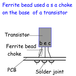
7b.3 Recall the use of ferrite beads or rings in internal and external filtering. On circuit boards it is often desirable to prevent RF passing along a wire - for example into a transistor or back along a wire to the 12v power supply. Ferrite beads can be placed on the (base )leg of transistor, turning the leg into a small inductor that will prevent RF passing because of the high impedance created. The same can be done in wires carrying power to a transistor amplifier. The wire is wound around a ferrite core to create a high impedance to RF current, but maintaining a low resistance to DC. |

|
|
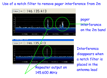
7b.4 Understand the use of notch filters including coaxial stubs as notch filters or traps in minimising an unwanted signal. A notch filter is designed to remove a particular frequency that is causing interference to radio reception or a harmonic from a transmitter. Example 1. In some areas radio paging transmissions on 138 and 153MHz can cause interference to the 145MHz amateur band. A notch filter tuned to a particularly strong radio paging signal in the 138MHz band and placed in the down lead to the 145 TX/RX can solve the problem. Example 2. Another example is where a 50MHz transmitter has a second harmonic at 100MHz which is causing problems to local reception of the VHF broadcast. Placing a notch filter in the transmitter antenna lead will remove this harmonic. Example 3 In a contest station the 40m station is having problems with breakthrough from the 80M station. Placing a notch filter in the 40m lead to the antenna tuned to 80m will reduce interference from the 80m transmitter. Obviously notch filters for receivers do not have to handle the same current as those built for transmitters. To make a stub, a T-piece is screwed into the antenna socket. This has one output to the receiver and two inputs. One of these is connected to the coax from the antenna and the other is connected to a length of coax called a stub. The length of the stub and the type of coax used will determine the frequency of the stub. The stub will absorb the frequency to which the stub is tuned. The formula for calculating the length of the stub is: Wavelength of the frequency to be notched out x velocity factor of the coax used to make the stub x 1/4 So, to make a filter to remove a broadcast station on 100MHz (3 metres) using a length of coax with a velocity factor of 0.66. This would be: (3 x 0.66) *1/4 = 0.495 metres or 49.5cm Cut the coax a little longer than this. Screw one end into the t-piece. Tune into the interfering signal by removing small section of coax until the interfering signal is reduced to its lowest level. |
  |
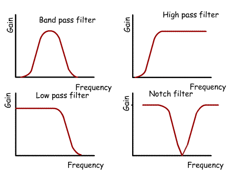
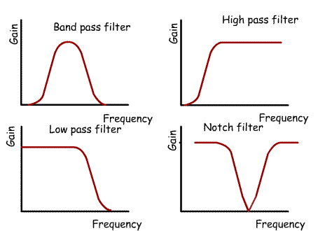
7b.5 Understand the use of high, low and band pass filters in improving the immunity of affected devices. We have already seen how low pass filters are placed between the PA stage and the antenna to reduce harmonics and spurious signals above the operating frequency. Band pass filters are placed at the front of receivers to allow only signals in that band to pass to the mixer stage, High pass filters can be used to remove signals causing interference below the operating frequency. Extra, external filters of this type can be added where there is a specific interference problem. For example: If a group of pager transmitters in 138 MHz band are causing interference on the 145MHz band an external high pass filter could be designed to attenuate signal below 140MHz. This would be placed in the 145MHz station antenna lead. Given that it would need to cope with the transmitted 2M signals it would have to be built with components that could withstand the voltage and currents from a transmitters. This would be built with inductors and capacitors. |
 |