| ADVANCED LESSON 71 |  |
| LEARNING OBJECTIVES and NOTES | |
| Measurements - Meters | |
|
10a.1 Understand the use of multiplier resistors in analogue
voltmeters, shunts in ammeters and the effect of the test meter on the
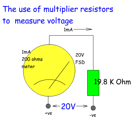
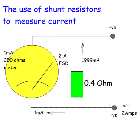
circuit under test. There are two types of meter in common use by radio amateurs: 1. Digital meters that produce their output on a digital display. These can be bought for £5-£10 from many retail stores. In addition to measuring current and potential difference (volts) they also measure resistance and frequently include inputs for testing transistors. The advantage of these is that the voltage is easy to read often producing the average of a number of readings; they are relatively cheap, they have a high input impedance which is not affected by the circuit they are attached to. 2. Analogue meters are based on a moving coil meter which moves a needle across a calibrated scale. These vary in price according to the size of the meter, the input impedance, the meter bearing used and the inclusion of a mirror behind the scale. The advantage of these is that for voltage and current readings they do not require any battery power; they enable the user to see more rapid changes in voltage and current. In addition the position of a meter gives the user instant information about the approximate voltage from a distance. A digital meter has to be read a close quarters to work out the voltage. We will concentrate on the analogue meter, although the digital meter uses a similar technique to create different ranges of voltage and current. All meters are rated to draw a certain current at full scale deflection (FSD) of the needle ie when the needle is as far over as will go. This value is very important as it has to be taken into account when adding multiplier resistors and shunt resistors to measure a specific voltage or current. Common meters have a FSD between 50uA and 1mA. they also have resistance so a 50uA meter is about 3.5kOhms and a 1mA meter is about 200 Ohms. Meters are normally used for DC voltage / current although a diode can be added to the circuit to convert AC to DC. Voltage multiplier resistors To measure voltage a resistor is placed in series with the meter. The voltage of this resistance is calculated for Ohms Law: For example to have a maximum reading of 20 volts using a 1mA meter the resistor would be: R=V/I R = 20/1 R= 20kOhms However the meter has a resistance of 200 Ohms so: 20,000 Ohms - 200 Ohms = 19,800 Ohms This is not a standard value so could be made up from an 18k resistor plus a 2.5k potentiometer. The potentiometer could then be adjusted to give a FSD at 20 Volts. A switch would be used to place a different multiplier resistor for each range required. Typical ranges might be 200mV, 2V, 20V, 200V and 1000V. The current rating of the resistor would need to match the current through the circuit. Current shunt resistors To measure current a resistor is placed across the meter. Most of the current will flow through the resistor, but a small amount will pass through the meter. Lets use the same meter as above ie a 1mA FSD with a resistance of 200 Ohms. the formula is: Rs = Rm / (Is / Im) Where Rs is the shunt resistance, Rm is the meter resistance, Is is the shunt current and Im is the meter current. For a 1mA meter, with a 200 Ohms resistance with a FSD of 2A. First of all if 1mA flows through the meter then 2000 - 1 = 1999 mA flows through the shunt resistor Rs = 200/ (1.999A / 1mA) Rs = 200 / 1999 Rs = 0.1 Ohms Resistors of this small size are often made out of a length of resistance wire, cut to length or a length of resistive metal cut and filed to achieve the desired resistance. Effects of the meter on the circuit under test We do not want the voltage or current to change because we have attached a meter across it. The higher the resistance of the meter circuit, the less effect on the circuit. A cheap digital voltmeter usually has a higher resistance than a cheap analogue meter. One can also build or buy a FET voltmeter. These use a FET with a high impedance between the circuit under test and the meter. For measuring lower currents a 50uA meter is more accurate than the 1mA meter used in our examples. |
  |
| Measurements - Frequency Checking |
|
|
10b.1 Recall the uses and limitations of absorption wavemeters,
heterodyne wavemeters, crystal calibrators, digital frequency counters
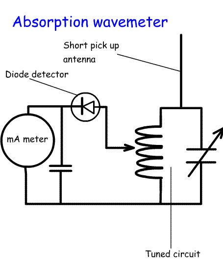
and standard frequency transmissions. A variety of tools are used for checking the frequency of oscillators, transmitters, receivers etc. here is a list of what they do and their limitations: Absorption wavemeters - the pick up antenna is placed close to the equipment. The variable capacitor and variable inductor are adjusted so that the meter shows a maximum reading. The tuned circuit scale is used to read off the frequency. This can also be used to check for harmonics, spurious and parasitic oscillations from a transmitter.
2MHz for top band 3.5 MHz for 80m 7.0 MHz for 40m 14 MHz for 20m 21 MHz for 15m 28, 29 and 30 MHz for 10m
Limitations - the reception of Standard Frequencies depends on ionospheric conditions. Sometimes you can't hear them! If this is the case try using the Radio 4 transmission on 198 kHZ. |
 |