Military Wireless in the Midlands Museum Virtual Site

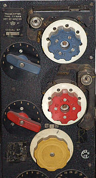
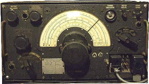
THE R1155 RECEIVER
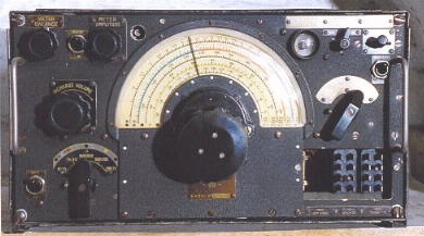
The famous set inside the Lancaster.
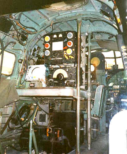
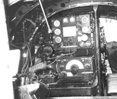
Other shots found on the web.
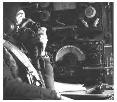
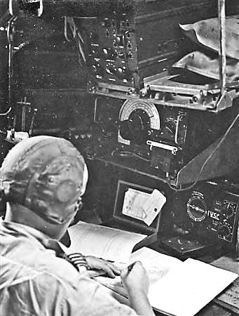
Inside the Hallifax:

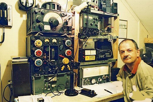
and inside the shack here. Still going strong after all these years.
LEFT: This R1155 arrived recently:
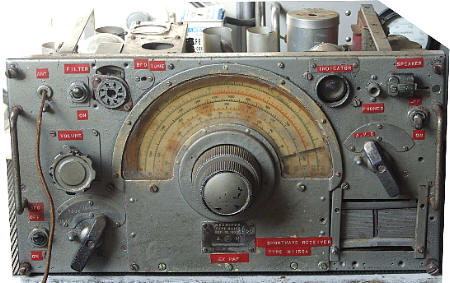
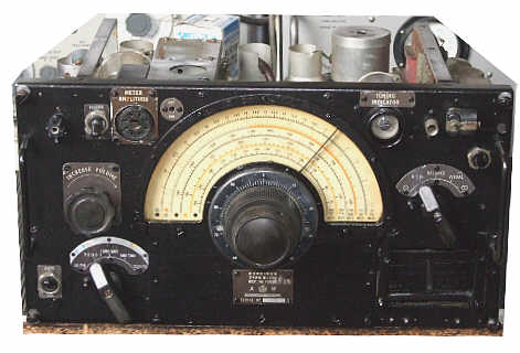
needless to say, it required a little work. It was working amazingly, with an added mains
power supply and and audio valve, type 42, from the ark. RIGHT: After a little work the set now looks like this:
Still some work to do but at least its looking like a 55 now.
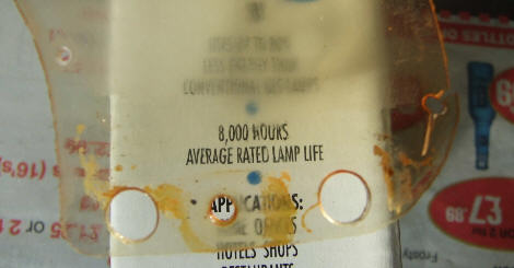
Interesting side note. While cleaning the silver paint off the perspex dial I had to rub hard. As a result the dial went very
opaque. I tried washing the dust off it but later, after it had dried again it was still very poor to look through.
I did notice though that as I ran a wet finger across the surface it went much clearer. I thought of what I could use, like water
but what would not in effect evaporate. I tried clear nail varnish, I use this to cover id plates after cleaning, keeps them from tarnishing again.
Anyway, I applied a touch of nail varnish to the lower edge of the dial as a trial. The picture is below. I think you can clearly see the difference
in visibility through the old perspex had greatly improved. If you have a dull visor you might try this. In the end I sprayed the perspex with engine sealant,
a clear lacquer and the whole dial is now usable.
R1155L, this is the version covering 160Mtrs. Quite nice condition, dial clear, scale fully readable, unfortunately the DF section had been
removed otherwise looked ok.
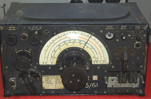
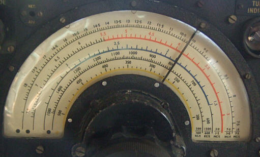
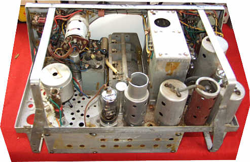
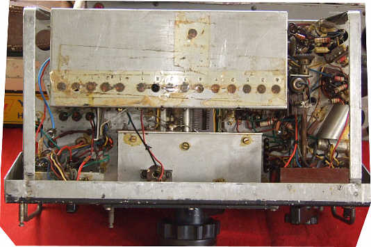
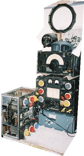
LEFT: The R1155 with the T1154 transmitter and loop aerial.
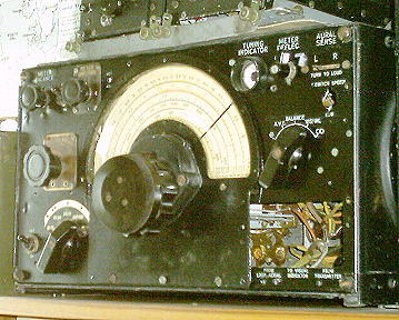
RIGHT: Another got at 55, this a R1155L.
BELOW: This a Model B, complete and fully working..............................................................................
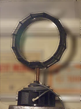
.........................................................................................................Close up of the loop aerial.
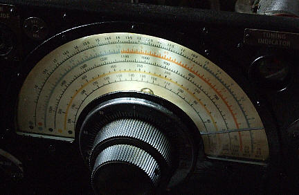
Light up that dial
Fed up with a dark dial (just how did the aircrew read the dial in the dim light of the Lanc ?) well here's one way.
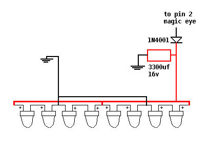
I used 8 white LED's wired in 4 sets of 2 in parallel. These can be fed from the heater supply, the magic eye is the closest
so pin 2 (check first) should have 6.3v ac on it, pass this through a diode, I used a 1N4007, then a bit of C to raise the volts and then off to the
diodes. After wiring the diodes together and fitting 2 small flying leads for pos and neg the tops of the diodes should be taped off
to prevent shorts then the string is bent into a gentle curve, this can then be inserted above the dial and behind the bunch of wires which
run along the top of the set. These wires will hold the diodes in place or a bit more tape can be used.
Futher Information.
There are several sites on the web with technical details so rather than just re-invent the wheel here are a few links where you can find all you need.
Send an e-mail to: Ben Nock, G4BXD
(If link does not work on your PC then send email to: [email protected] )
********* Pictures by G4BXD are G4BXD copyright ********


needless to say, it required a little work. It was working amazingly, with an added mains
power supply and and audio valve, type 42, from the ark. RIGHT: After a little work the set now looks like this:
Still some work to do but at least its looking like a 55 now.
Interesting side note. While cleaning the silver paint off the perspex dial I had to rub hard. As a result the dial went very opaque. I tried washing the dust off it but later, after it had dried again it was still very poor to look through. I did notice though that as I ran a wet finger across the surface it went much clearer. I thought of what I could use, like water but what would not in effect evaporate. I tried clear nail varnish, I use this to cover id plates after cleaning, keeps them from tarnishing again. Anyway, I applied a touch of nail varnish to the lower edge of the dial as a trial. The picture is below. I think you can clearly see the difference in visibility through the old perspex had greatly improved. If you have a dull visor you might try this. In the end I sprayed the perspex with engine sealant, a clear lacquer and the whole dial is now usable.

R1155L, this is the version covering 160Mtrs. Quite nice condition, dial clear, scale fully readable, unfortunately the DF section had been removed otherwise looked ok.


LEFT: The R1155 with the T1154 transmitter and loop aerial.


RIGHT: Another got at 55, this a R1155L.
BELOW: This a Model B, complete and fully working..............................................................................


.........................................................................................................Close up of the loop aerial.
Light up that dial
Fed up with a dark dial (just how did the aircrew read the dial in the dim light of the Lanc ?) well here's one way.

I used 8 white LED's wired in 4 sets of 2 in parallel. These can be fed from the heater supply, the magic eye is the closest
so pin 2 (check first) should have 6.3v ac on it, pass this through a diode, I used a 1N4007, then a bit of C to raise the volts and then off to the
diodes. After wiring the diodes together and fitting 2 small flying leads for pos and neg the tops of the diodes should be taped off
to prevent shorts then the string is bent into a gentle curve, this can then be inserted above the dial and behind the bunch of wires which
run along the top of the set. These wires will hold the diodes in place or a bit more tape can be used.

Futher Information.
There are several sites on the web with technical details so rather than just re-invent the wheel here are a few links where you can find all you need.
Send an e-mail to: Ben Nock, G4BXD
(If link does not work on your PC then send email to: [email protected] )
********* Pictures by G4BXD are G4BXD copyright ********
(If link does not work on your PC then send email to: [email protected] )