| Dymar/Burndept 2000 Mods for the
2m band
These radios were made for the Power Authorities who, until recently,
used the PMR mid-band, ie mobile TX on 107MHz and mobile receive on 139MHz.
With the coming of the expansion of the VHF Band II broadcast band to 108MHz
they lost their lower frequency slot, so these and a lot of other equipment
became redundant.
Part 1 - Getting In.
Remove the top and bottom covers from the radio. At the back of the
set remove the 2 self-tapping screws that hold the top aluminium plate
in place, also remove from this plate the 2 countersunk screws that hold
the top boards in place, remove this plate. Some sets have a selective
calling board fitted, this is indicated by the set having an extra thumbwheel
switch on the front panel and a "CALL/RESET" toggle switch beside it. also
inside there will be a larger board beside the long narrow synthesiser
board. If the SELCALL board is fitted remove the 2 screws which hold it
to the front panel and carefully lift it out as it has wires attached and
lay it beside the set. The smaller board is the synthesiser board. Undo
the screw that fixes it to the front panel and lay it beside the set as
it also has wires attached.
Synthesiser Modifications.
Remove the four countersunk screws in the lid of the synthesiser box
and remove the lid, also unsolder and remove the screening plate from underneath.
Look at the layout diagram and remove C227 (39pF) and fit a 15pF in it's
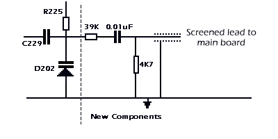
place. Also change C248 (18pF) to 12pF. From the junction of D202, R225
& C229 connect a 0.01mF capacitor in series with a 39k resistor as
in the diagram below, also connect a 4k7 resistor to ground. From the junction
of the 0.01mF capacitor and the 4k7 resistor connect a 12" length of screened
audio cable with the screen connected to ground, feed the other end of
the cable through the grommet in the front of the box. Solder the screening
plate back to the underside of the board. Then fit the new EPROMS marked
A & B in their respective sockets (pin 1 towards the front of the box).
This completes the synthesiser modifications.

|
Receiver modifications
Refer again to the layout diagram and remove the link between tags
16 & 17 (if fitted). If the SELCALL board is fitted trace the wires
coming from this to tags 19 & 20 and remove these leads and tape them
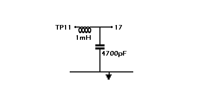
up, then link tags 19 & 20 together. Connect a small RF choke (approx.
1mH) between TP11 and tag 17, then connect a 4700pF or similar capacitor
from tag 17 down to earth, as in the diagram below.

Transmitter modifications.
If you once again refer to the layout diagram in the bottom LH corner
of the board you will see (if fitted) a small PCB marked BRD2. This is
the transmitter timeout board which is a bit inconvenient so may be unsoldered
(3 connections) and replaced with link 5 as indicated on the main board.
Next remove the cover over the transmitter PA, which is held in place
with 3 screws along the side and 2 screws in the back panel.Now comes what
is my least favourite bit. At this point I recommend you get a cup of coffee
and study the layout diagram and the actual board as we have to change
the value of 8 capacitors. The capacitors to be changed are listed below,
and make sure you know their locations and in particular the tracks under
the board. Use either solder braid or a solder pump to desolder the old
capacitors, taking care as there is a screened lead running under the board
which I found kept getting in the way. Replace them with the values listed
below:-
C85 change to 12pF
C86 change to 47pF
C92 change to 12pF
C93 change to 47pF
C94 change to 12pF
C100 change to 47pF
C148 change to 47pF
C108 change to 10pF
* *C108 is inside the can of L23, leave the can off for the time being.
Now remove completely the following components:-
C156 (27pF)
R107 (3K3)
Now change the value of the following:-
R103 change to 10K (If deviation still high change to 3K3 or 2K2.)
Now the coils to be modified:-
L14, L16, L17, L20, L21*, L22, L23, L24.
Carefully unsolder the coils one at a time, so you donít lose their
positions, and reduce the number of turns by one turn for each coil. Then
re-solder each coil back into the board. I found it useful to slide something
inside the coil when removing the turn, my trimming tool was just about
right, but anything will do to stop the coil from getting squashed. *L21
on some sets is just a loop, if so, leave it alone. Replace the screening
can over L23 The other end of the screened lead from the synthesizer should
be connected to TP21, with the screen connected down to earth.This completes
the modifications.
Alignment to 2M
Assuming that you have fitted the new EPROMS into the synthesizer in
their correct sockets, as on the layout diagram, with their notches to
the front. Make sure the boardsare safe and not touching anything, connect
your 12 Volt supply and switch on. Select channel 20 on the channel indicator.
Connect an AVO 8 or similar Multimeter to TP205 on the synthesizer board
with the negative lead to the chassis or earth. Adjust the core of L203
carefully anticlockwise until the meter reads about 6.5 volts. Also check
that the red LED near the front of the board is now out.
* !!!!!!! Ensure an adequate dummy load is connected !!!!!!!*
Then key up the transmitter and adjust the core of L201 anticlockwise
with the meter still on TP205 until the meter reads 6.5 volts. Again, check
that the red LED is now out. (This is the synthesizer "out-of-lock" indicator.)
Adjust the core of L203 until the core is about 2mm out of the can. This
completes the synthesizer tuning.
Receiver tuning.
Leave the channel set to 20, connect your meterís positive lead to
the positive end (the end with the stripe) of D18 (near TP8). With no signal
this should be approximately 4.5 volts. Then connect a signal generator
or similar to the ant lead tuned to 145.500 MHz and increase the output
until the signal is heard. Feed more signal in until the voltage on D18
starts to fall. Adjust the cores of L1, L2, L3, L4, L5 and L7 for minimum
voltage on D18, reducing the output of the signal generator as the gain
comes up, and keeping the voltage on D18 above 3.5 volts. Repeat the tuning
above again for optimum gain. If an oscilloscope is available connect it
to TP8 and with the signal generator still connected to the ant socket
with about 2.5KHz deviation tune T6 for minimum distortion. If a scope
is not available connect an aerial to the antenna socket and go through
the channels until a known good local signal is heard and adjust T6 for
best quality audio. Set the mute adjust pot (RV6) so that the front panel
mute control works at about midway, there is a bit of hysteresis on the
control anyway, so donít be too critical. This completes the receiver modifications. |
Transmitter tuning.
Connect a power meter to the antenna connector capable of reading up
to
about 25 Watts. Connect a diode probe to TP15 (if diode probe not available
see diagram below for simple circuit to connect to your AVO).

Key up the transmitter and adjust L9 for maximum Now move the probe
to TP16, key up the transmitter and adjust L10 and L12 for maximum. At
this point there should be a slight output indication on the wattmeter,
if not, put the diode probe near (or on if no reading) L16 with the transmitter
keyed up and adjust trimmer C95 for maximum. Now you will have an indication
on the wattmeter. Now tune C96, C98, C103, C104, C105 for maximum output.
If this exceeds about 15 Watts turn down using RV5. These trimmers tend
to interact so I advise going through the above sequence several times
to get the optimum. As a word of warning it is fairly easy to get either
the PA oscillating or an output on a lower frequency than wanted, check
this with a counter with probe near the output. When I had this condition
happen I found that the trimmers were screwed down. The correct position
is roughly mid-travel, so repeat the above tuning and look for a second
peak nearer mid-trimmer. When sure you have a nice output on 2M set this
to 15 Watts with RV5 and seal the trimmers with quick drying paint, i.e.
model enamel, or nail varnish, whatever is at hand. Then check the RF output
and replace the screening cover and screw down, check the RF output again
and quickly slightly re-adjust before the paint dries.
Then check the deviation with either a deviation meter or a friend on
the air. This is set using RV4. If fitting a toneburst feed the 1750Hz
into pin 32, the selcall input. If your set still had the original selcall
board fitted it is possible to set this to send a string of "7ís" which
correspond to 1748Hz, near enough for most repeaters. Remove the code plug
PL401 and hard-wire the socket(SK401) as shown below. Cut the track below
the board that runs from pin 20 of IC406 to pins 9/10 of IC408.

If the tone is off frequency link together TP408 and TP409. Connect
a frequency counter to pin 32 (white lead), making sure you have a dummy
load connected to the aerial socket, press the call button, the transmitter
will key for a few seconds, then drop out leaving the tone going on the
counter. This can now be adjusted with RV404. When set, remove the link
and adjust the toneburst modulation level with RV403. The tone will now
operate each time the call switch is pressed. On some sets you will have
to remove link 401 to get results.
|


