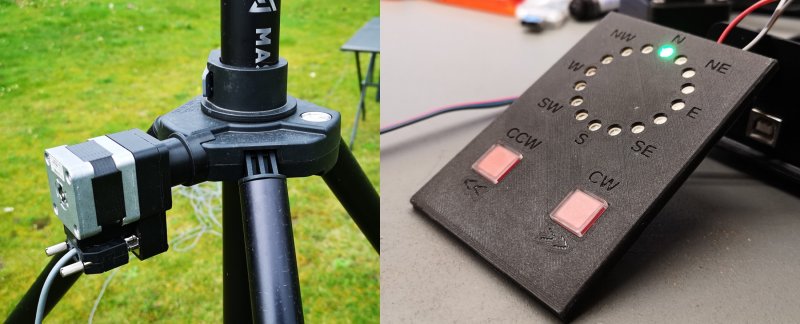
A button press on [CCW] or
[CW] makes the rotor move 22.5 degrees either ccw or cw.
I will allow a rotation of 360° minus 22.5°, 15 steps on
each side from N. A short press on the [CW] button wil move
the Rotor 22.5° clockwise and then stop. The first LED cw
from N goes ON. Continuously pressing the [CW] button keeps
the Rotor moving and the LED's indicate the movement
in 22.5° steps. After a movement of 270° cw from N over E
and S to W, the Rotor is moving out of the "safe sector". It
can still be moved further on to N - 1 step, but the
LED color turns from blue to bright red. The last
allowed position 22.5°, one LED left and right of N, gives a
clear indication in what direction the rotor has to be be
moved to get in the safe sector. From here on further cw
movement is blocked.
And vice versa.
Have a look at this short video:
https://youtu.be/9pHU1JZAdzU
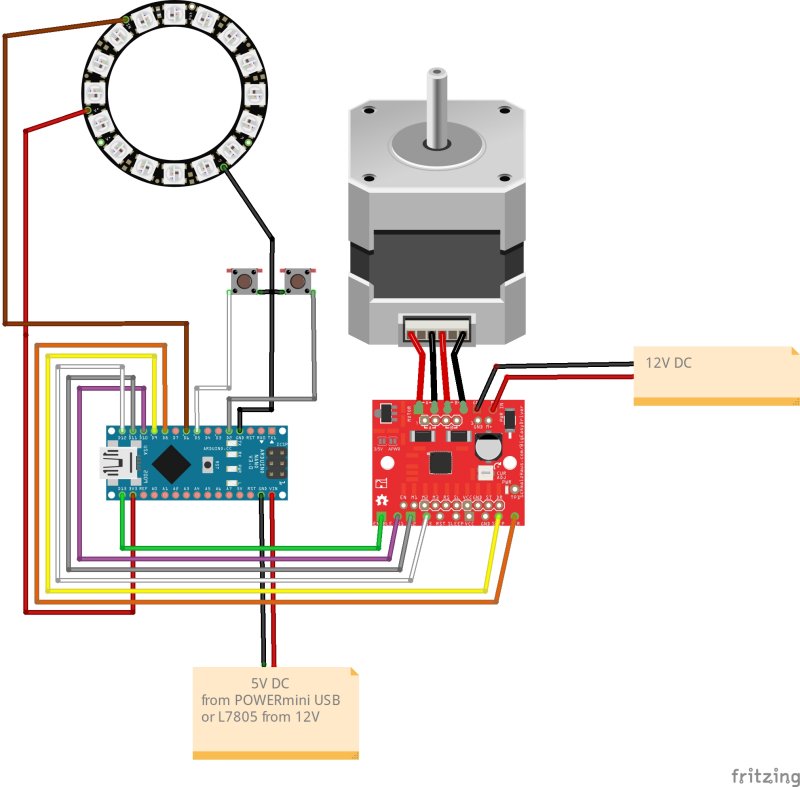
The hardware is extremely simple:
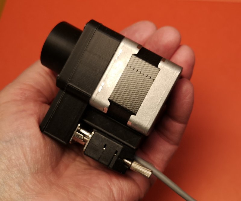
On the rotor side
- 1
NEMA 17 42x42x34 or 42x42x40 Stepper Motor
- 1
Adapter like the one David is using for his DC-Rotor,
modified for the stepper motor
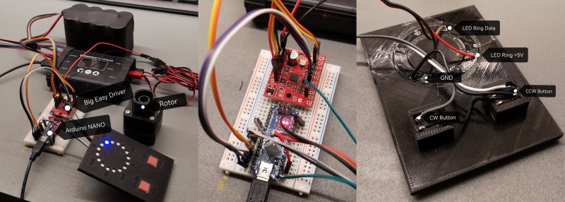
On the controller side
- 1
Arduino NANO or UNO
- 1 Big
Easy Driver
- 1
NEOPIXEL 16 LED Ring
- 2 Push
Buttons
Rotor and controller are connected with a 4 core cable
Power supply
- 12 to15
V DC for the rotor, same as for TRX
- 5 V DC
for the Arduino
all available from the PowerMini, but I am using a positive
voltage regulator xx7805 1.5A to power the Arduino (Vin)
from the 12 V line.
Simple pin to pin wiring between the components:
- 5 wires
between Arduino and face plate with LED ring and
buttons
- 6 wires
between Arduino and Big Easy Driver
- 4 wires
between Big Easy Driver and rotor
- 12V to
Big Easy Driver
- 5V to
Arduino
Simple wiring
The wiring is clearly documented in my
Arduino
Sketch.
For more information about the
<Adafruit_NeoPixel.h> library see:
https://github.com/adafruit/Adafruit_NeoPixel
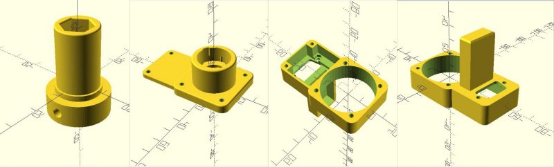
The controller case
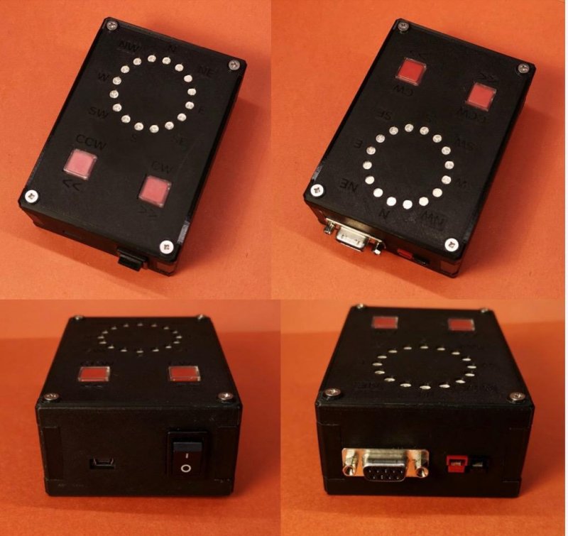
Controller Case
I made a 3-D printed case for my controller, a remix
of the
(tr)uSDX
case.
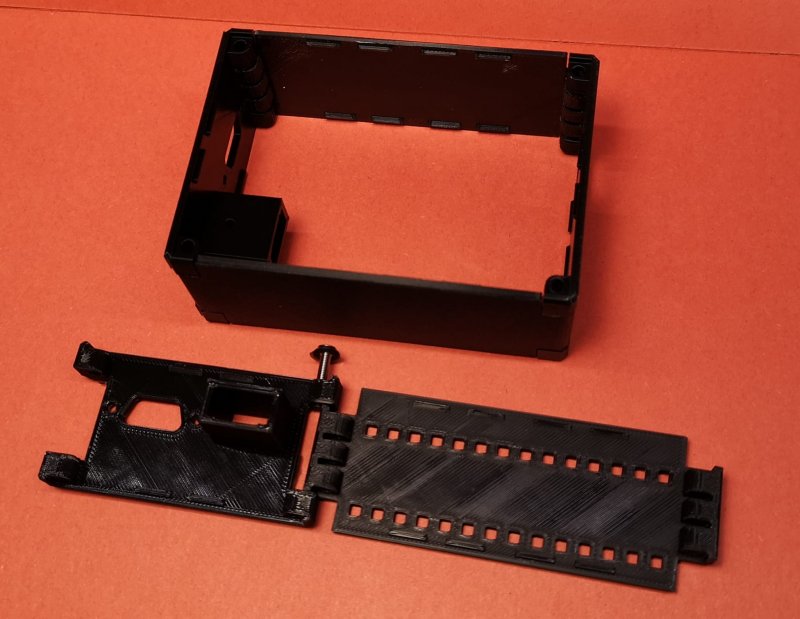
Case, (tr)uSDX style
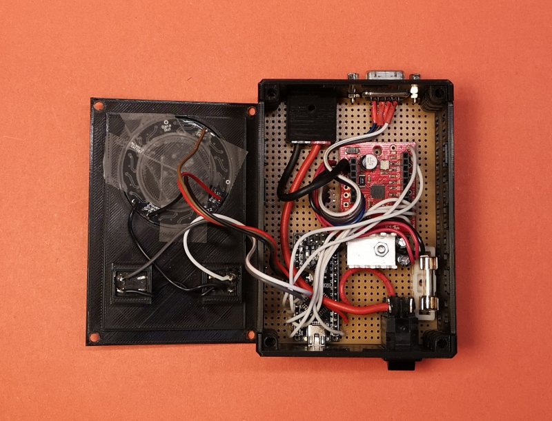
Inside viev
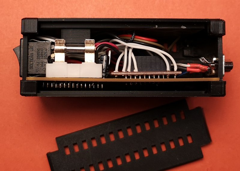
Side view, showing position of the breadboard
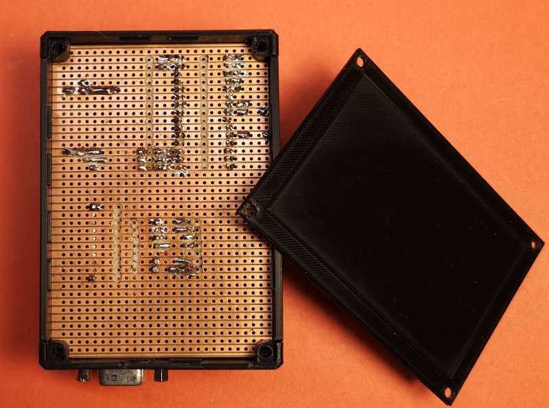
Bottom view
Unfortunately,
all the Neopixle Rings have (slightltly) different
dimensions, the same applies to the push buttons
and other parts you find in your junk box. So the
STL-Files might not fit your parts and you might
have to remix the STL's.
Here you can download
the STL.Files of the Case
If you are familiar with
OpenScad, pse. contact me for the SCAD.Files.
1st Results of Field Test
There is not much to tell. The setup was working as
expected. After 2 1/2
hours of operating the stepper rotor did not loose one
step!
The resolution of 22.5° is absolutely sufficient.
This video shows the movement of the rotor: https://youtu.be/-c7IjqDggso
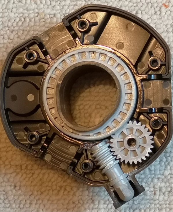
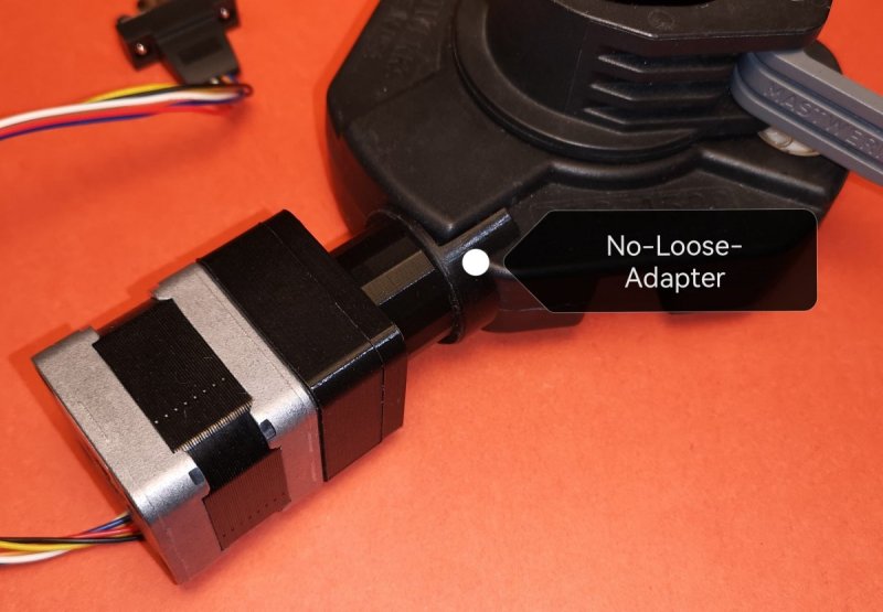
The No-Loose-Adapter
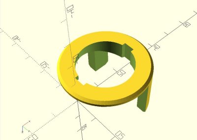
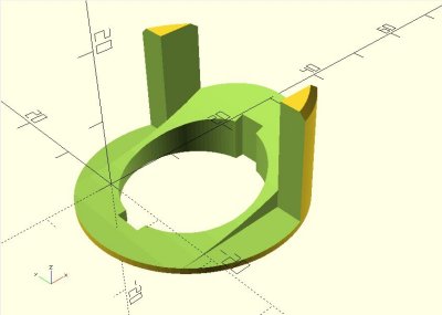
The No-Loose-Adapter fills the gap between the hub and the
Rotor
The No-Loose-Adapter is a gadget I have been using almost
since I got my first MASTWERKS mast five years ago.
I did not like the loose feeling of the crank handle so
I made a 3D-prited part to fill the gap between the hub
and the crank handle. I have my No-Loose-Adapter
permanently attached to the hub. It is mandatory for a
firm fit of the rotor.
Here you can download
the STL-File.