NOISE BLANKER
Some Yaesu FT-736/R version might be improved on system of the Noise Blanker.
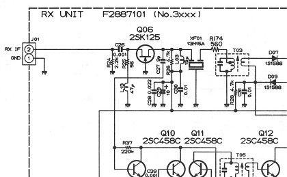
In fact if you observe the sketch, the I.F. signal (13.690 MHz) was taken on
filter called XF-01 through the resistance RNB and C27 (9 pF) but was not
enough to drive the amplifier stage and noise CNTL blanker.
Instead on the partial schematic (see RX-Unit) anything is right and the
capacitor C27 takes the signal directly on the drain of the FET 2SK125 (Q06).
Actually I do not know why, Yaesu Musen has imported some versions with this
modify already made. Probably a strong signal might cause distortion of modulation,
when the noise blanker is actived, anyway this brief modify (original restore) does not
cause problems, neither with local Hams and I got good results and an excellent performance
on my transceiver.
As was before

Now after the modify
FREQUENCY COVERAGE
Frequency coverage modification for 141-154 MHz:
Arrange the following diodes in the 2 meter unit as follows;
Frequency coverage modification for 430-450 MHz:
Frequency expansion modification is available for a range of 430-450 MHz only. If this
frequency is acceptable, arrange the band presetting diodes in the UHF-UNIT as follows:
Install diodes at position D8008, D8010, and D8011.
D6025, D6026, D6027 and D6030 might be installed, instead D6031 might be removed.
Any FT-736/R transceiver with the electronic Keyer installed, has problems
when the speed is over 500 LPM (we have already done speed test with OH5IY
and 9A4GL MS-DSP software) even so a lot of Hams is working without any modify
to 1000...1500 LPM. However we have known someone that complains when use VOX an older one (manufactured in later half of
1994) doesn't work above 700 LPM. Probability the cause is not only to
reduction C82 value on TX-Unit to 4.7uF, but also through a switch should be
excluded the Keyer-Unit and removed even the twisted jumper wire on the
board, near at P01. But following these suggestions you will have not any
problems with speed until to 5000 LPM.
Keyer-Unit (all X point should be cut off)
Example of switching MS - Normal CW
(To put on rear pannel)


The carrier ON-OFF keying often called CW, requires bandwidth of:
Best feature with TNC-2 to 9600 Bps
On the FT-736R we have usually two sockets on rear panel for digital signals
which, 6-pin DIN jack that provides serial I/O connections for computer within data
rate of 4800 bits/sec and one socket data IN/OUT mini jack, which allows direct
connection TNC without emphasis signal until to data rate of 1200 Bps.
However, whether you got a TAPR TNC-2 running to 9600 Bps and you did not
anything, very probably you will have a few headaches. In others words
if you want certanity of working and to minimize any mistake, you should follow
these three suggestions:
to replace IF-FM ceramic filter (CMY-55F) with a filter at last 20 KHz to -6dB type CFW-55C or similar.
to pick up digital signal directly on discriminator, output point of L14-C82, through 10 KpF capacitor (see RX-UNIT).
to inject digital signal (AFSK from TNC) directly on the common point
R32-R33, through normal cable BF.
1) To replace the ceramic filter
2) AFSK output towards TNC
3) AFSK Input from TNC
Just in this way, we have had few proof testing and somebody still attempting connects to 38400
Bps on Super Volley Links. However if you will have again trouble during the reception
of the digital signal (a lot of retries) and your TNC-2 is all right, probably is just the time
of to replace wholly discriminator FM circuit (write to me a few lines !!).
Another example AFSK, but only till 1200 Bps
Any modify issued on this page has been done personally.
Bn= B * K ,where
Bn= necessary bandwidth in Hz
B = speed in bauds (calculated from speed LPM (Letters Per Minute) (WPM=LPM/5)
K = keying sharpness factor (5 in fading circuits like MS)
in fact
B= LPM / 6 = 5000/6 = 833.3 bauds
The required bandwidth is 4166 Hz (4.2 KHz)
Raising the speed to 10000 LPM will increase the bandwidth to 8.2 kHz.


IK6MLI, Joe.