E. Girlando Home Page
19/10/2004 22.42.34 +0200
|
Back to E. Girlando Home Page |
|
This page has been last updated on: 19/10/2004 22.42.34 +0200 |
PANASONIC NV-L20
VCR type G-chassis
An experience in reassembling and re-synching the main gear
Torino (Italy), November 2002
This procedure applies to a
G type VCR deck that had, for any reason, jumped teeth (lost sync). This brief assumes the main pulley gear, including idler, take up and
supplier and all the correlated stuff, being intact. Should you dismount it, you'll not find here any instruction about how to re-assemble it.
Cleaning and lubricating are out of scope of this brief.
For a brief introduction to the g-chassis see at the bottom of this document.
It took me three weeks of hard work at night to document this procedure. If you'll find it useful for your purposes, please honor me with a few bucks donation via Paypal. Thank you.
Take all the metal arms and all the cog wheels of the lower main transmission gear out of the
deck.
Remove the metal cover on top of the cassette carriage gear and take the sliding cassette carrier box out of its seat.
Then remove the entire cassette carriage gear (black plastic) from the deck.
You need to unscrew the four screws as indicated.

Remove the pinch roller gear entirely. If needed remove, clean, lubricate and reinstall the two
tape levers (also known as "tension arms", " tape loading
arms"). I had to replace the leftmost one as its base peg has got broken
during the teeth jumping (I understood this is a quite common fault).
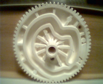
Here are some pictures of the initial setup.


With the carriage out of the
deck you should be able to easily move its white arms along their entire (now idle) stroke.
Push the cassette carriage gear white arms down in the cassette-in position. To achieve this turn the white arms so that the right one
(looking from the deck front) reaches the end of stroke and stays locked down by
the plastic black hook.
We can take advantage of this time to check the correct engagement between
plastic
and metal gears: the last notch of metal rack engages the last but one tooth of the plastic arm's quadrant
cog.

This are sample of the correct
position in my unit:


The carriage gear is linked to the main gear by mean of
a dark gray cog wheel.. Called "the link cog", it is a steel cog ..
even if it
looks like gray plastic, when you have it in you hands you will get
surprised about its weight.
The synchronism markings on this cog are: one marked notch and one tooth marked
with a dimple. On the other side
(not shown) another small dimple marks the position of the same reference notch.

Reinstall the cog and the carriage gear keeping the cog so that the reference notch
axle is perpendicular to the deck edge with the reference notch on the outside
and engaged with
rightmost teeth of the quadrant rack of the carriage metal gear.
 ..and
looking from the other side
..and
looking from the other side 
This positioning is critical to
success: it took me plenty of attempts before I have found the correct one.
Turn the deck upside down so that you can work from its bottom side. Click
the solenoid latch manually and turn the main gear
pulley clockwise, as seen from the bottom of the deck, until the gear "stop-clicks" into neutral position. To verify
the position check
this: turning clockwise
only one cog below the pulley turns and nothing else happens; rotating counter-clockwise the idler
rotates engaging the take up that rotates as well; nothing else or different should
happen.
With this set up you are ready to start the reassembly.
| 1 | mount the base cog of sun&satellite gear (also known as "ring gear"); align its two mounting reference holes to the chassis reference holes underneath; |  |
| 2 | mount the status cog/cam (also known as "sub cam gear"); maintain alignment between its single mounting reference hole and the chassis mounting reference hole underneath; at the same time maintain alignment of the synchronism reference holes of this cog with BOTH the base cog of sun&planets gear mounted previously AND the cassette carriage dark gray link cog wheel. Unfortunately the last match has to be checked on the opposite side of the deck. Good luck in turning the deck upside down avoiding the cogs just installed to fly away! |  |
| 3 | mount the status change latch; allow it to drop into its place |  |
| 4 | mount the planets cog; maintain alignment between mounting reference holes of BOTH the holes of the cog underneath AND the chassis holes under-underneath |  |
| 5 | mount the big cog/course cam (also known as "main cam gear"); maintain alignment of the single mounting reference hole AND the corresponding hole in the cog underneath AND the chassis mounting reference hole under-underneath; at the same time align the sync reference hole with the corresponding sync reference hole in the planets cog |  |
| 6 | mount the tape load cog/cam; maintain alignment of sync reference hole with the corresponding sync reference hole in the planets cog; keep the tape loader arm underneath in the most extended position (no force should be experienced during the operation -risk of damage here!). |  |
| 7 | mount the sun cog into the planets gear; maintain alignment of the two mounting reference holes with the corresponding holes of the cogs and the chassis underneath. At the same time align the sync reference hole with the corresponding sync reference hole in the main gear cog; lock it into position installing with the locking washer (or C-ring). |
 |
| The main gear train is
now completed. We can proceed with the pinch roller and the rightmost tension arm gears. There is a double cog (also known as "pinch speed down gear or cog") linking the main and the pinch roller gears. It has to be mounted from the top of the deck, but the sync hole matching with the main gear is visible from the bottom. So this is the point of the job where you have to work on both sides of the deck. This can be challenging as the cog is not kept in the spindle when you turn the deck upside down. |
||
| 8 | mount the double cog linking the main gear train with the pinch roller cam gear; maintain alignment so that the notch identified by sync hole of the lower cog engages with the tooth identified by the sync hole of the cog/course cam mounted in step 5. |  |
| When done you can turn the deck in its normal working position as far from now on you have to work from the top. This is a top view of how things should look like after step 8. |  |
|
| 9 | mount the leftmost tape lever driver arm; if you dismounted it, insert the plastic arm and drop it into position so that the notch identified by the sync reference hole engages with the first tooth of the lever's metal arm rack. |  |
| Before going further we have to spend a few words to describe the pinch roller spiral cam. It has a couple of sync reference points. The first is a hole visible looking at the tower from the top and it marks one notch in the cog. Exactly on the opposite side of the cog, one of the teeth is a little taller than the adjacent ones. That is the second sync mark. There is also what seems to be a third sync mark visible from the bottom, but it resulted unuseful for mounting purposes. |


|
|
| 10 | mount the pinch roller cam so that the taller tooth matches the notch marked by the sync dimple in the double link cog mounted in step 8; on the diametrically opposite side of the cam cog, the notch identified by the sync reference hole engages with the tooth identified by the sync reference hole of the mode switch. When inserting the roller cam into its spindle, care must be taken not to brake the pin of the black plastic frame as it interferes with the operation. Besides the leftmost tape tension lever has to be kept to fully extended position while the cam drops into its definitive position. At the end the stuff should look as shown. |


|
| 11 | reinstall the pinch roller gear fastening it and the pinch roller cam installing the plastic stop in their shafts | |
| 12 | Reconnect the deck, reinstall ...pray... and test it. |
WOW!! Today is November the 11th 2002 and my unit works like it worked when it was brand new!!!!
introduction to the g-chassis
Many subversion exist: this brief is based on my direct experience with my unit. Differences may apply to your unit.
Looking the deck from the bottom at a glance, you should be able to identify:
This mechanic is like a finite sequential
state machine. States are sequential steps in the tape loading process.
It is able to step from one state to another turning the main pulley, clicking
the solenoid gear and continuing turning the pulley until the main gear
"stop-clicks" into a neutral position. The rotation direction
establishes the direction in the statuses sequence.
Assuming you have the deck in the eject position, turning the main pulley by
your fingers, you'll find that turning in one direction the cassette carriage
reaches the end-of-stroke in the eject direction while turning in the opposite
direction the carriage move toward the cassette-in position. Be careful: to
proceed to the full cassette loading, you have to defeat the three protection
locks the carriage encounters in the rails during its travel: the first is on
the right, the second in on the top-left, the last on the right.
Once the cassette is fully loaded, continuing turning the main pulley will move
both the tape load lever arms to an intermediate position, where, after a
"stop-click", the gear stops moving even if you continue turning the
pulley. That's the signal you have reached state one. To proceed to the next
state you have to continue turning the pulley and simultaneously "click" the solenoid gear. As soon as you click the solenoid, the main
gear starts to move again toward the next state that is reached at the
next "stop-click" .
You can continue like this until the last state is reached. To came back from the
last state to the first, reverse the pulley rotation, going back,
"stop-click" after "stop-click", until you reach the
cassette-out position again.
The torque you apply to the pulley DO NOT have to be excessive or something is
going wrong in the gears. Be careful not to continue to apply torque once the
extreme statuses are reached.
|
Back to E. Girlando Home Page |
to the top of this page |
This page has been last updated on: 19/10/2004 22.42.34 +0200 |